,
3-Axis Accelerometer
As its name implies, an accelerometer measures acceleration. A 3-axis accelerometer will measure longitudinal, lateral, and vertical acceleration. The table below explains these accelerations and their positive/negative definitions by automotive convention.
|
The 3 Axes of Acceleration |
||
|
Type of Acceleration |
Direction of Acceleration |
Definition of Positive and Negative |
|
Vertical |
Up or Down |
Up is positive acceleration, Down is negative |
|
Longitudinal |
Forward or backward |
Forward direction is positive, backward is negative |
|
Lateral |
Right turn or Left turn |
Left is positive, Right is negative |
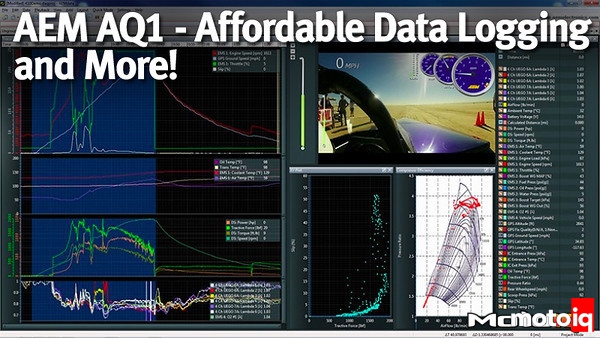
This information is very important to understand how the vehicle body is moving in relation to the road. It is also useful to look at logged data in relation to speed and accelerations, such as when you are trying to evaluate aero loading under braking or acceleration. Below we show an example of this, taken from a recent track event where Jager Racing was interested in tire loads in relation to track position and body movement.

AEMnet Compatibility
My knowledge of CAN bus systems is limited, but from my understanding, CAN bus is basically a communications wiring network that allows devices connected to the line (bus) to send and receive data to each other. For a data logger, CAN bus is powerful because it can allow devices that need to communicate with many things to also be logged. In addition, it makes it easier to send data from multiple different sensors in different locations to the data logger. AEM calls its version of CAN bus, AEMnet.
Out of the box, the AQ1 can read 8 analog sensors, 3 digital sensors, a device connected to a serial plug, and devices connected to AEMnet. By connecting the AQ1 to other AEM devices through AEMnet, the amount of channels of data that can be logged vastly increases. For example, if one uses the AEM Infinity as their ECU, this can be connected to the AQ1 on AEMnet. This adds 128 available channels of data from the Infinity to be logged by the AQ1! Also, one can log AEM’s X-Series of gauges through the AEMnet, which saves room for the other 8 analog channels to be devoted to other sensors. Table 1.5 gives a list of AEM products that can connect to the AQ1 via AEMnet.
|
AEM products that can connect to AQ1 via AEMnet |
|
X-Series UEGO AFR Gauge |
|
X-Series Oil/Fuel Pressure Gauge 0 to 1000 psi |
|
X-Series Oil/Trans/Water Temp Gauge 100 to 300 F |
|
X-Series EGT Gauge 0 to 1800 F |
|
X-Series Boost Gauge -30 inHg to 35 psi |
|
X-Series Oil Pressure Gauge 0 to 150 psi |
|
X-Series Boost Gauge -30 inHg to 60 psi |
|
X-Series Boost/Fuel Pressure Gauge 0 to 15 psi |
|
X-Series Inline Wideband UEGO AFR Controller |
|
X-Series GPS Speedometer 0 to 160 mph |
|
Vehicle Dynamics Module |
|
4 Channel Wideband UEGO Controller |
|
Wideband Failsafe Gauge |
|
Universal Programmable Engine Management System. EMS 4 |
|
Infinity ECU (all Models) |
|
Series 2 Plug and Play Engine Management System |
Now that we’ve gone over the features of the AQ1, we can now go over how data can be used to improve a team. In section two, we’ll go over how data is an integral part of the development at Jager Racing, and how we use it to constantly improve.
Sources