,
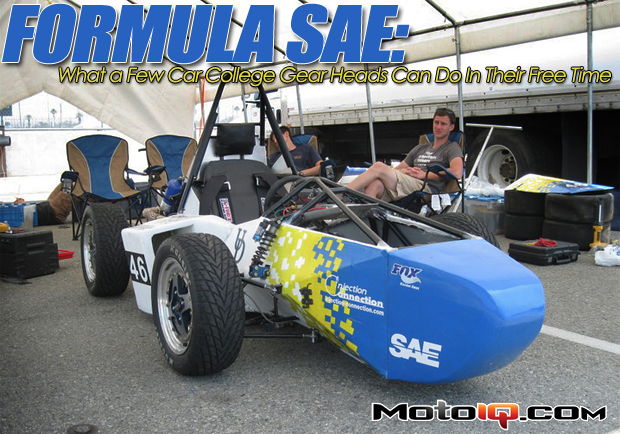
This series will focus on the car itself (how it was built, some of the decisions made, etc.), and conclude with the competition in California and the trials the team faced there as well as the results. Before we take a look at the car, I must apologize for the crudeness of some of the parts on the car. As these pictures were taken(January – February 2011), the team was under a strict deadline to have the car running and some things were thrown together at the last second to make it move. However this was also the best time to show the inner workings of the machine. Rest assured no cardboard or zip ties appeared on the car in California! Okay, well maybe a few zip ties…
In Part 1, we will be focusing on the chassis and suspension. UD’s car is based off a chromoly steel tube-frame chassis. Some teams use a composite monocoque, but due to time constraints and cost, UD decided to stick with a tube-frame. This frame was designed using SolidWorks 3D modeling. It was put through multiple FEA tests to test twisting resistance, while keeping the weight down. The bare frame weighs a mere 70 pounds. All the tubing (except where mandated by the rules in the roll hoops and certain key frame members) is thin wall chromoly steel. Chromoly was used to keep costs low without compromising strength. The FEA was done with chromoly in mind and the car passes all FSAE rules. There is a cost report in competition and each team must validate every dollar spent. This is another reason UD currently uses a tube-frame. Taking full advantage of SolidWorks, each tube was printed individually and used as a template for making the part in the shop. This allowed perfect mitering and less time wasted measuring and guessing. A horizontal band saw is used to cut the tubes slightly over-length. A tubing bender is used for creating the bends. Notching is done with either a lathe or a notching tool and the fit is perfected using a bench grinder. The frame was built in a wood jig and every tube was TIG welded by the students.
 |
|
The front bulkhead is steel plate. A foam crush structure will be bolted on per SAE rules. A fiberglass nosecone will sit over the crush structure. UD has had a number of rules written because of its cars. We used to use the battery as an impact attenuator until the rules banned “non-crushable crush structures.” You can see all the triangulation done to keep the frame strong yet light. The welding is not perfect, but remember this was done by students, not professionals. |
Suspension is critical to any racecar. Unlike modified road cars, SAE cars can use nearly any suspension system they can dream of. Most teams stick with the tried and true double wishbone suspension. UD is no different, using unequal length A-arms front and rear, as well as pushrod suspension. The suspension is one of the most heavily fabricated parts of the car. Everything except for the bearings, rod ends, and dampers are custom made and designed by the team. The suspension is designed for low ride height, no bump steer, and good camber gain. Ride height is very low, just over two inches. The pushrod rocker is designed to increase spring rate. The rocker also actuates the solid sway bars. The end links are custom built and adjustable. The suspension arms are made from hollow tube steel, with threaded steel inserts welded inside. The hollow arms keep unsprung weight down and the clevises that locate the arms to the upright are removable. Specially made shims are used to adjust camber. All suspension links use spherical bearings for precision. A second advantage to using spherical bearings is that fabricating links and brackets for bearings is very easy. The spindles are custom made from steel and the front hubs are also custom made from aluminum round stock. The hubs are very light, weighing about half a pound each. They are optimized for strength and weight savings. The design also reduces stress risers that could cause a failure. Wheel studs are from Fastenal. The uprights are also cut from aluminum. They weigh about one pound each. In all, each corner of the suspension weighs around 20 pounds with a wheel and tire bolted on. This is as much as most cars uprights alone! All parts in the suspension were FEA tested in Solid Works with a fairly large margin of safety. No TorroRosso-like failures here!
 |
|
Lots of fabricated and engineered goodies here. The front suspension uses unequal length A-arms and pushrod actuated suspension. The uprights, steering knuckles, hubs, spindles, control arms, pushrods, rocker arms, brackets, and the swaybar are all custom built. The only off the shelf parts here are the wheel bearings, rod ends, and the Fox Shocks. All the bolts are Grade-8, from Fastenal. By adjusting the length of the heim joints on the suspension arms, settings like KPA and caster can be changed. Camber is adjusted by inserting shims between the upper or lower clevises and the upright. |
The upright, hub, clevises, swaybar end links, rocker, and steering arm are all custom made on a CNC mill. Each upright starts off as a solid piece of aluminum which is first clamped to the mill so the mounting holes can be drilled out. The drilled stock is then bolted to a jig and set in the mill where it is slowly carved into the finished upright. To go completely through the material requires three passes and takes about two hours. The hubs are made in a similar fashion, but must go back and forth between the mill and the lathe. All the blue anodizing was done in-house with a homemade anodizing tank. Resident genius Jay did all the anodizing and it does look sharp!
 |
|
Sway bars and adjustable end links are all custom fabricated. The end links are custom machined from aluminum and anodized in UD blue. Note the keyway to prevent slipping. The bar itself is solid steel. The end links are thinwall tubing just like the control arms (but with a smaller OD) with welded-in threaded inserts. Spherical bearings for all! |


1 comment
can u please send me the parts of customised pedal box