,
Fuel System Calibrations
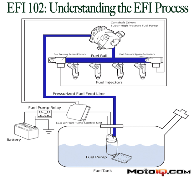
The input triggers for most modern EFI fuel systems usually come from the Camshaft Position Sensor (CMP) and Crankshaft Position Sensor (CKP). These input triggers are set-up to let the ECU know when it should open the fuel injectors for each cylinder. Inputs from the main load sensors (MAF or MAP+IAT) are used by the ECU to generate an initial output for the fuel injector pulse, this output is usually measured in milliseconds. The ECM will then make compensatory adjustments based on additional sensor inputs including: Intake Air Temperature (IAT), Engine Coolant Temperature (ECT), Throttle Position Sensor (TPS), Knock (KNK), System Voltage, Heated Exhaust Gas Oxygen (HEGO), etc. The ECU will modify the fuel injector pulse width based on the look-up values in these compensatory tables then final adjustments are made according to learned information stored inside the ECM; Short Term Fuel Trim and Long Term Fuel Trims. These final adjustments are usually made by the ECU in order to achieve emissions targets.

Ignition Advance System Calibrations
The input trigger for most modern EFI ignition advance systems is usually the Crankshaft Position Sensor (CKP). This input trigger is set-up to let the ECU know what position the pistons are at (in relation to TDC) so it can fire the ignition event at the appropriate time (before TDC). Inputs from the Main Load Sensors (MAF or MAP+IAT) are used by the ECU to generate an initial output for the ignition event, this output is usually measured in degrees before top dead center. The ECM will then make compensatory adjustments based on additional sensor inputs including: Intake Air Temperature (IAT), Engine Coolant Temperature (ECT), Throttle Position Sensor (TPS), Knock (KNK), System Voltage, Heated Exhaust Gas Oxygen (HEGO), etc. The ECU will modify the timing of the ignition event based on the look-up values in these compensatory tables then final adjustments are made according to learned information stored inside the ECM; Short Term and Long Term. These final adjustments are usually made by the ECU in order to produce as little emissions as possible and protect the motor from damage.

Boost Control System Calibrations
The input trigger for most modern EFI boost control systems is usually the Crankshaft Position Sensor (CKP). This input trigger is set-up to let the ECU knows what RPM the engine is at so it can reference a boost measurement (MAP) against a boost target. Inputs from the Throttle Position Sensors (TPS), MAF, or MAP sensors can be used by the ECU to generate an initial output for the wastegate duty cycle, this output is usually measured in percentage (0 being fully open, 100 being fully closed). The ECM will then make compensatory adjustments based on additional sensor inputs which could include: Gear Position, Intake Air Temperature (IAT), Engine Coolant Temperature (ECT), Knock (KNK), Barometric Pressure, etc. The ECU will modify the percentage of duty cycle sent to the wastegate solenoid valve based on the look-up values in these compensatory tables then final adjustments are made according to learned information stored inside the ECM; Short Term and Long Term. These final adjustments are usually made by the ECU in order to achieve the dictated boost target. All boost control systems operate differently and this should be used as example of one type of boost control logic.