

Drift cars with their extreme steering angles are pretty difficult to design suspension for. A lot of things must be considered because geometry that works well on a regular car can have bad side effects at extreme steering angles. Some of the issues are excessive tire tilt that reduces tire contact patch (one of the reasons why drift cars have so much static negative camber) and can cause the front end to wash out skate, Excessive weight jacking to the wrong side of the car in drift which reduces rear traction, Excessive front lifting which can overload the power steering system, overcentering and wheel wobble, poor self-steer, excessive Ackerman build up, the list goes on and on.
For our team, our car handles pretty well but since Formula Drift competition is becoming so fierce, we decided to revisit our front end geometry to see if we could get any more advantages for the 2019 season. We have had a CAD model of our front suspension for several years and CAD has been responsible for helping with many of the car’s improvements but we wanted to quickly play around with actual hardware to help us visualize things better and to actually be able to change the shape of our front suspension upright on the fly. Yes, we had done this in CAD but nothing beats being able to look at, measure and play around with the actual parts on the car.
So our goals would be to keep the tires flatter on the ground at full lock, make a little more angle, quicken the steering ratio, reduce weight jacking and stress on the power steering pump. From CAD we had an idea of how we wanted to configure the upright but we wanted to play with actual pieces on the actual car.
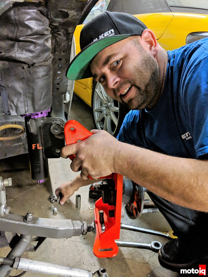
Chris Eimer from Eimer Engineering created a simple dimensional representation of the upright from the CAD drawings of the existing part in three pieces that were slotted so they could be moved around a lot to change the shape and where the offset, trail, Ackerman and steering arm length could all be easily and independently adjustable. He then printed it on his 3D printer to make some test fit parts.

Chris assembled the upright then bolted the hub to it. Of course, the plastic isn’t strong enough to hold the weight of the car but it is strong enough to cycle the suspension.
18 comments
And in a not far away future, you go from this to a metal 3D print and call it a day 🙂
3D printing is really a revolutionary approach that we are starting to see in so many fields.
It’s hard to get 3D printing strong enough right now, my idea is to 3D print then HIP the part to get rid of voids and improve the grain structure. We are considering this for another project.
Oh just saw this so forget my comment further down.
It’s not that hard to produce parts with proper strenght?
It’s important to get a parts producer who can do HIP. https://www.mimotechnik.com/ in Long Beach should be able to help you.
But otherwise parts with 99.8% density are the norm in the SLM business right now.
Yup 99.8% is just like a bad casting! So much for me thinking I am being a smart guy with HIP if it’s SOP, hahaha!
We can get more dense. But that’s what we guaranty
But it’s depending on what the customer wants to do with his parameters
HIP is done mostly for materials with high immer tensions
https://slm-solutions.com/fileadmin/user_upload/downloads/en/200EN180924-02-POWDER_WEB.pdf
You find strengths here.
An awesome use of 3d printing, it brings the digital CAD world into something that can be physically manipulated and modified in a relatively quick turn around time. I did have a few questions though
first, this sentence confused me a bit:
“The knuckles are made of fabricated hollow 4130 Chromoly plate. ”
Did you mean that the knuckles are a hollow design made from 4130 chromoly, or is the plate actually hollow?
Also, what are your thoughts on potentially using machine learning for suspension tuning? given a multitude of variables to control and a specific goal to achieve it seems like it could be beneficial to get a computer to compute the best result from the infinite possible permutations.
Mike, you can see in the last picture which shows their CAD sort of “final design” that it is a hollow design, just being that it isn’t cast, and has some lattice laser cut holes instead of being a cast unit, or a billet piece pocketed out.
I’m not sure setting machine learning would be super useful. You’d have a lot of parameters to enter, you’d have a lot of ‘hard points’ to enter, and rules bounds to put in, and in the end you’d still be faced with 2 distinct problems.
1. The steering performance, feel, etc, will come down to some subjective figures based on the driver’s input. Look at the difference between Vaughn Gitten Jr, and Chelsea Denofa twin Mustangs, versus this teams car. Or even looking at the same platform the team Roush mustang. Gitten and Denofa’s mustangs regularly pick up a front tire when loaded up and drifting, JTP’s Roush mustang stays very flat. Which one is better?
2. Technical feasibility of producing whatever the machine learning happens to determine is ‘best’. For as many parameters you can feed a machine learning program, there are some which will be too hard to communicate, and ‘ease of construction’ seems always something which will not come through. Great to make a really organic shape with micro-lattice to carry the forces while minimizing weight, and generate designs and shapes you didn’t think of, but may be virtually impossible or just too expensive to produce.
I think for complex multi-variable issues, a humans intuition can be better. As for set up, my personal opinion is if the car is jacking a ton and lifting the inside front wheel, it is not making use of the front wheels and it is also overloading the outside rear wheel and the car isnt hooking up well past the initial dynamic hit, its losing traction in steady state. These things make the car harder to drive as well.
It is made out of fabricating plate enabling the part to be hollow. I think at this point humans are better than computers at set up. I edited it to make it more clear now.
Why didn’t you ask someone like Mimo-Technik to actually 3d-print it out of metal?
https://www.mimotechnik.com/
Less fabrication, stronger and more lightweight design…
They already do some stuff for BBI and are located in Long Beach
Like I said earlier with metal 3D printing, it is hard to get rid of small voids within the material so the mechanical properties are not as predictable and it is possible to get an intergranular failure, also there is no useful grain orientation. So a 3D printed part is like a bad casting not the best for highly loaded parts. One of my ideas is to HIP the part after printing it. The other issue is 3D print a large part like this is time-consuming and expensive. We are probably going to 3D print and HIP some uprights for another project you might hear about soon! For production 3D printing is going to help make the core box and stuff.
https://www.youtube.com/watch?v=hPkY8nBWxoU
grain orientation needs to be adressed by HIP but thats SOP
(disclosure: I`m actually doing metal 3d-printing for a living at SLM Solutions)
But the mechanical properties are predictable if you have a competent machinist who has his parameters and post processing under control. Our customers have parts flying in planes with all the necessary qualification.
So I’m really interested what you guys will come up with.
Great for testing if you are a manual guy, I did the same thing all in cad with collision detection and could output camber, caster and shock angle (it was double wishbone) curves to excel, I was damn proud of myself… until Ohlins told me my shock angle was stupid and it would never work. To be fair it was my first job and I had no idea how to do it without a computer, or what all those curves meant. I mean suspension setup is still grey magic to me but “If you can’t make it precise, make it adjustable.”
I see people mess up the shock motion ratio all the time, especially when they try to build rocker arm suspension. Nearly all of those are in falling rate because whoever doesn’t understand what they are doing.
I like your locating shims for the steering linkage. Looks more consistent, accurate and fast compared to bolting down a nut in the slot.
I have always wondered how drift cars could be driveable with typical caster angles at those huge steering angles.
While I have no idea what the ‘ideal’ drift setup is, I have a feeling that Ackerman probably isn’t helping. Interesting that they run Anti-Ackerman in F1.
I have always wanted to play with Ackerman on a dedicated racecar. I have a feeling that the optimal setup cannot be found without building new uprights, since OEMs do not anticipate race rubber, and the associated slip angles needed to extract maximum lateral cornering force.
3d printing a suspension componenet… if its designed with all the stuff around with a 3d scanner modeling is a lot easyer. Also just by measuring camber you have no idea of geaometry, self centering efects and lockup at high angles.
Only thing that make sens is to build knuckles that are like the ones listed here but out of proper metal to get it working on a real life rest sesion. Thas what we doo for rallycars, lower pickups and control arm brackets are bolted to the knuckle so we can varry kingpin, castor, camber (without kingpin) , trail arm, accarman, steering rate. Its a lot of iteration but fine adjusting is the only way by testing on track.
Of course, we know all the factors of suspension geometry, we have a parametric model of the suspension in cad, we just do 3D printing to confirm stuff.