,
Designing the more reasonable engines that most of us drive requires the use of an extraordinarily complex control device that is able to constantly sample ambient weather conditions, understand driver inputs (you pushing on the go pedal), and control the engine no matter what gas is in it or even if part of the engine is not working properly or is even broken. You can think of this process as a constant optimization that has to work under all conditions…not a simple task.

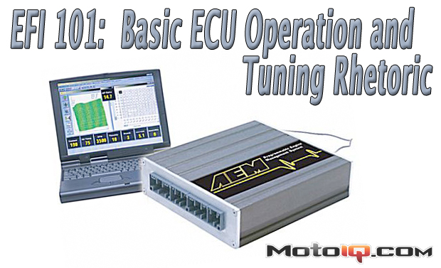
This series of articles is intended to help you understand basic 4-cycle, Spark-Ignition (SI), internal combustion engine operation and their electronic engine control systems. To do this we will first introduce you to the different terminology used by tuners, engineers, & engine calibrators found in this glossary. This article will use 2D animations, table screen shots from various ECU calibration software, and simple drawings to explain how a modern engine is calibrated and to demonstrate basic mechanical movement. You will also be introduced to some basic physics, chemistry, and mathematics that are frequently used in SI engine calibration. A long-term objective of this series of articles is to go over Electronic Fuel Injection (EFI) basics then focus on how each of these basics applies to modern engine management strategies of each manufacturer, and even to specific engine designs.

All modern vehicles consist of mechanical parts which move while under the control of a electrical control system. The major mechanical parts are known as the engine or motor; the electrical control system is called the Engine Management Systems (EMS), which is also referred to as an ECM, ECU, EEC, or Engine Computer. These two systems must work in harmony. The engine is designed to take into account the mechanical properties which the hardware is made from and the abilities of the modern electronic feedback systems. The EMS must be programmed to understand how it will be triggered through its inputs, what hardware it is controlling, what environment it is operating within (weather conditions, elevation, fuel quality) and when the mechanical thresholds of the engine hardware are exceeded through sensor feedback systems.

Modern EMS systems use various feedback systems to implement a closed-loop control system. The closed-loop control system will usually have targets (or goals), a means of measuring the engine’s performance, and the ability to adjust the engine’s performance in order to achieve its targets.