,
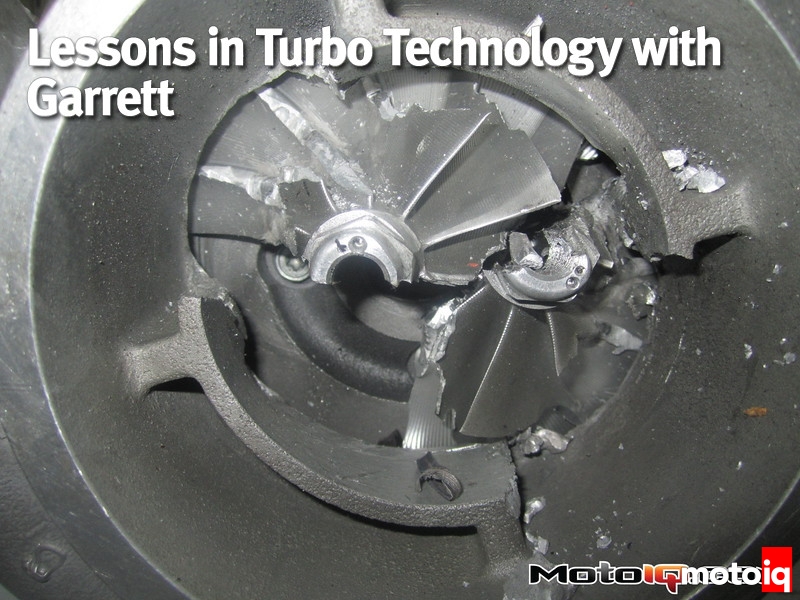
The last major cause of burst is foreign object damage or FOD. If a compressor wheel ingests a rock or piece of rubber kicked up from the racetrack, or an exhaust valve fails at redline and is blown violently into a turbine wheel, of course, the wheel will be damaged but additionally, there is a chance it may actually burst.
A projectile hitting a wheel spinning at tens or hundreds of thousands of rpm can do much more damage than easily imaginable. If the hit is hard enough or strikes the hub just right, a wheel can burst due to significant weakening. The best FOD prevention for the compressor wheel is using an air filter or at least a wire mesh screen, and thoroughly checking any pre-turbo plumbing for debris. Even a rag sitting in the engine compartment during a dyno pull can quickly be sucked into an open compressor and cause major FOD.
 The turbo is mounted to the test cell. The turbo is powered during the test by a gas generator which uses a large combuster to generate hot gas to spool the turbo up to the desired speed.
For the turbine side, ensuring that the engine is built to handle the power and temperature being demanded will help to prevent FOD from internal engine failure. Properly engineering the valvetrain and internals for the target RPM and temperatures with proper safe tuning will minimize the chances of the engine shooting bits of itself into the whirling turbine wheel.
Although not strictly fitting the definition of burst containment, housings should also contain the damage caused by other types of wheel failures which have their own distinct root causes. Shaft and hub weld failures usually result from over-speeding the turbocharger so extremely that the bearing system cannot effectively support and control the spinning wheels and shafts any longer.
The shaft moves and bends in ways it was not meant to handle, and the wheels can literally crash into the housings since they too are moving and distorting past the allowable limits. Compressor and turbine wheels usually run at clearances less than 40 thousandths of an inch (0.040 in, or 1.00 mm) from their housings so the limits of allowable shaft motion and wheel distortion are very sensitive and must be respected. The use of a turbocharger speed sensor will reveal if the unit is in danger of overspeed.
Bearing failure will also result in excessive rotor group motion and potential wheel failure, but high-quality clean oil at the recommended temperatures and pressures will go a long way towards keeping bearings alive.
Wheel-to-shaft joint failures can otherwise result from quality issues compromising the strength of the wheel, shaft, or weld or from improper material selection – it is the duty of the turbo manufacturer to specify materials and treatment processes that will allow the rotor group loading for the intended engine application.
 Thick mesh scatter shields are placed around the cell to absorb any fragments that may escape if the housings fail the test. The shields are there to be witness parts to help visualize where any fragments might go. These shields have seen some failures. Prior holes are painted so any new holes can be observed with no confusion.
Burst Energy
At the heart of every turbocharger is a rotor group, which is just a pair of spinning wheels connected by a shaft and supported by bearings. Given the right conditions either wheel can burst, with the potential to release a large amount of energy. In order to design turbine and compressor housings properly, this amount of energy must be known and quantified, so that the housing can be made strong enough to contain the burst energy and elastic enough to absorb all of the fragments in the event of a burst. The specific type of energy stored in a spinning turbine or compressor wheel is called rotational kinetic energy, and can be calculated using the following equation
E sub k=1/2 Iw squared
Where Ek = the kinetic energy of a spinning object, I = the moment of inertia of the spinning object, and ? = the angular velocity of the object (the speed or RPM at which it is spinning)
Determining I, the moment of inertia, can be done using 3D CAD software to quickly calculate the value from the original 3D model, or by spinning a real wheel on a test rig and measuring the amount of power needed to get it to a known speed. For calculating I, we can think about the turbine or compressor wheel of a turbo as a spinning solid cylinder to make the math in the example much simpler. The moment of inertia of a spinning object is its resistance to applied torque. For a solid cylinder this is calculated by the following equation:
I=1/2mr squared
Where I = the moment of inertia of the solid cylinder, m = the mass (or weight) of the solid cylinder, and r = the radius of the solid cylinder (1/2 of the outer diameter). Plugging the equation for simplified moment of inertia into the equation for rotational kinetic energy, we get:
E sub K=1/4mr squared x w squared
From this, we can see that the energy contained by a spinning turbine or compressor wheel is not only approximately proportional to the mass of the wheel but also that its energy is proportional to the outer radius of the wheel squared and the rotational velocity (or RPM) squared. This is significant because if two wheels are spinning at the same speed and have the same mass but one is twice as large as the other, then the rotational energy of the larger wheel will be four times that of the smaller one. Similarly, if a specific wheel accelerates from a given speed up to four times that speed, it now possesses 16 times the rotational energy that it did at the slower speed.
Rotational kinetic energy can quickly become huge at the speeds experienced by turbocharger wheels. But why should a turbocharger manufacturer care about the kinetic energy of a spinning turbine or compressor wheel, and why should turbo users care? Because all of that energy is released during a wheel burst, and it has to go somewhere. You don’t want it to go into and damage other parts of your car and especially not into your or other’s soft squishy bits.
Housing Design – Absorbing Burst Energy
Of course, that “somewhere” that the energy of a wheel burst will first go is into the housing. If the turbine or compressor housing is too thin, too brittle, too weak, too hot, or if the material is defective, it will not be able to effectively absorb all of the violent kinetic energy released by a wheel burst. Consequently, it will provide little protection for the turbocharger’s surroundings if fragments of the wheel come through the housing without losing much of that energy. If you are a part of those surroundings, well that will suck.