,
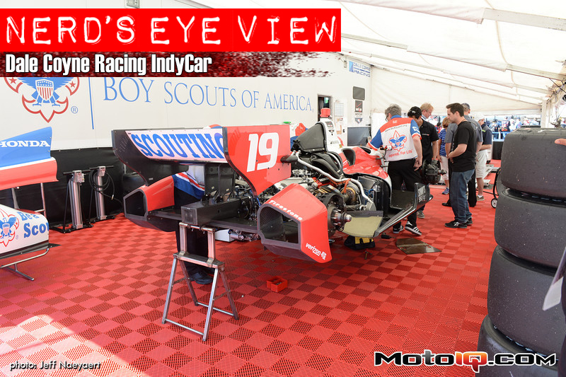
 As the turbos are pushed forward, it makes for a very difficult compressor inlet pipe design. They work just fine though! Just below the inlet is the turbo speed sensor. Looking back at the turbine side, you can see the turbine housing bolts are safety wired to ensure the bolts do not come loose.
 Enough with the engine stuff and onto the suspension. This is the rear of the car (obviously) and the two dampers have been removed for service. In their place are simple rods to hold the suspension up. The suspension is one area that is relatively open for unique setups with each team designing their own bell cranks and selecting their own dampers.
 A third spring setup is used on both ends of the car. In this particular case, a simple foam type spring is used in the current configuration. And yes, that is a whole mess of wires running over the drivetrain. Everything that can be measured is measured.
 For example, individual wheel speeds are measured. This sensor is reading the toothed cup on the rear axle. Back to the suspension, you can see the mounting point for the control arm and how there are multiple location options in order to adjust the suspension geometry.
 You can clearly see the three mounting location options here. Up by the bell crank is an adjustable hard stop screw that can limit the suspension’s droop travel.


