,
 Each arm was welded up on this jig. Yes it’s plywood, but it’s 5-ply which is very strong and won’t warp (unless you get it soaking wet). We designed this jig to work with both upper and lower arms, using the steel spacers. To get the desired roll and camber curves, the upper arms need to be welded at an angle. It’s possible to get that angle through clevises, but doing it in the arms is a lot easier, especially without fancy 5-axis machines.
Want a great way to get the design and tech judges to hate you? Do this. Putting rod ends in shear is an awful idea (according to the judges, bolts in single shear and rod ends in shear mean your design is automatically a minimum points design in their eyes). The torque of the brake caliper will snap the outer rod ends like twigs and that means no brakes and no steering. We were originally going to use these for testing to ensure our track width matched our axles and hubs. In previous years we had a lot of problems getting this right and would have to space the axle or upright to make up the difference. This is far from ideal, so the idea of having adjustable control arms was appealing to ensure we got it right. In reality, I screwed up the lengths in CAD and they were way too long, so they became scrap and a waste of a week's work. Measure twice, weld once!
 Thank god we never used these. This would have likely ended in tears. What’s surprising is that a number of GTA cars have control arms similar to this. It is possible to spec a rod end big enough to handle the shear, but spherical bearings are stronger and can be sized much smaller and therefore lighter.
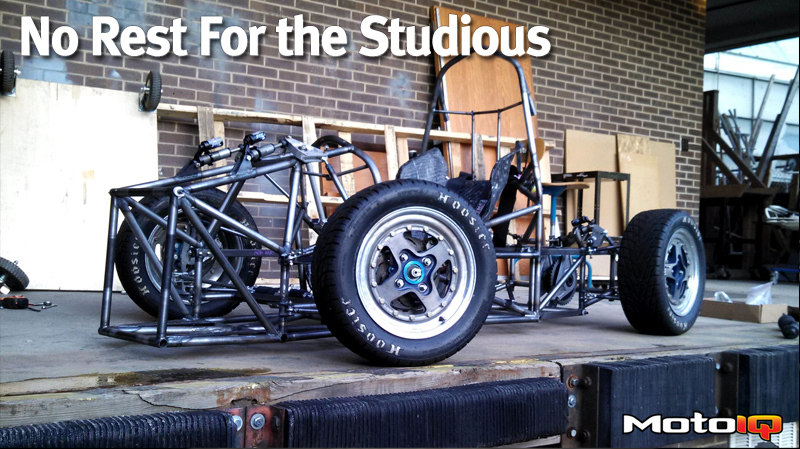
Our actual control arms used weld-in spherical bearing receivers from Light Racing on the upright side. The threaded inserts on the chassis side were made in our shop, but Pro-Werks also makes them if you’re short on time or tools. Note how the forces on these arms run along the length of the control arm (remember, they are two-force members, so the force runs along the length of the tube). MUCH stronger. After welding, we gusseted the the V of the arm for added strength. The screw up with the test arms wasted our thin tube, so we ended up making the new arms out of 0.065 wall tube anyway. Things were getting seriously rushed at this point. After a bit of trial and error, we finally got to here! The lower mounts are simple steel tabs welded directly to the frame. There is enough room between the rod end and the mounts that anti squat and dive can be adjusted. We designed for and eventually raced with no anti front or rear, as suspension movement in these cars is pretty limited to begin with and if we really needed any, we could shim into what we needed. The upper mounts are steel tabs too, but bolted on. Our advisor wanted camber adjustment without needing to remove the wheels. With these mounts, we could also adjust caster to some degree. On the upright side, we can also shim for camber, as well as KPA. While the arms are heavier than we wanted, at least the clevises holding the upright to the control arm are aluminum (in older cars they were steel. FEA analysis helped us design an equally strong clevis that was half the weight of steel). The uprights are leftover from our 2012 car and the design actually dates back to 2008. They’re over designed, but we have plenty of other areas we can improve in before we jump on losing a pound or two from the uprights. The brakes use Wilwood PS-1 calipers and custom made 9” rotors on custom made hubs, all left over from 2012. The PS-1 is perfectly sized for SAE cars and it’s hard to find a lighter caliper that’s anywhere near as cheap. UDSAE has been using these for over a decade with great success.
After a bit of trial and error, we finally got to here! The lower mounts are simple steel tabs welded directly to the frame. There is enough room between the rod end and the mounts that anti squat and dive can be adjusted. We designed for and eventually raced with no anti front or rear, as suspension movement in these cars is pretty limited to begin with and if we really needed any, we could shim into what we needed. The upper mounts are steel tabs too, but bolted on. Our advisor wanted camber adjustment without needing to remove the wheels. With these mounts, we could also adjust caster to some degree. On the upright side, we can also shim for camber, as well as KPA. While the arms are heavier than we wanted, at least the clevises holding the upright to the control arm are aluminum (in older cars they were steel. FEA analysis helped us design an equally strong clevis that was half the weight of steel). The uprights are leftover from our 2012 car and the design actually dates back to 2008. They’re over designed, but we have plenty of other areas we can improve in before we jump on losing a pound or two from the uprights. The brakes use Wilwood PS-1 calipers and custom made 9” rotors on custom made hubs, all left over from 2012. The PS-1 is perfectly sized for SAE cars and it’s hard to find a lighter caliper that’s anywhere near as cheap. UDSAE has been using these for over a decade with great success.