,
 Here’s some of the bits and pieces we had CNC machined in our Montrose, CO location. On the left are the bits and pieces that make up the pivot assembly for the roll-stiffness mechanism, on the right is the assembled pivot.
 Each tubular link has a heim joint (rod-end bearing assembly) at each end. The stepped “bung” is threaded internally, and is welded into the end of the tube. A jam nut is threaded on the shank and then assembled into the bung, as shown on the right. By putting a left-handed thread assembly at one end and a right-hand thread on the other, we can adjust the length without having to remove one end from the chassis.
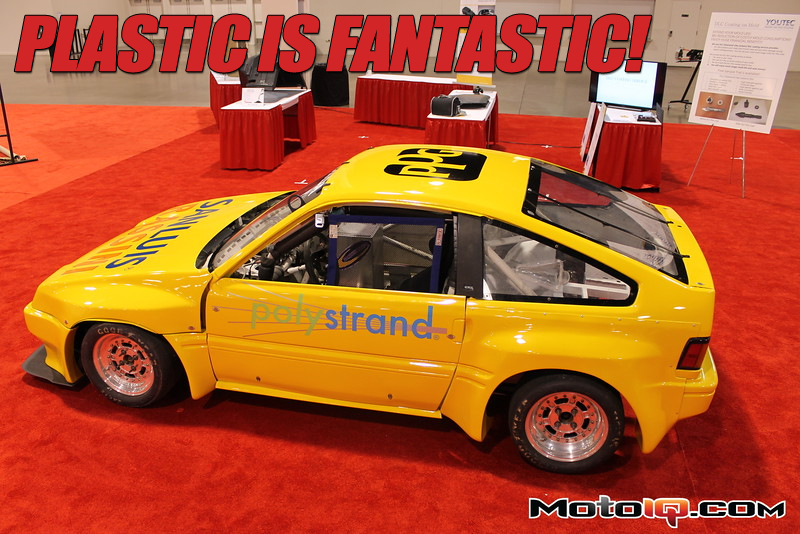
With a little bit of good planning, and a large dose of good luck, everything seemed to come together on schedule. I wrapped up the fabrication of the tubular links – making sure that each link was fitted with left hand and right hand rod-end bearings (heim joints) on opposing ends. Doing this ensures that any linkage adjustments needed at the track can be made without having to remove anything from the vehicle – we can just loosen the jam nuts on the rod-ends and turn it one way or the other to lengthen or shorten the link. Of course, always remember to tighten the jam nuts when you’re done adjusting (I actually had a car right in front of me on the racetrack lose one end of a panhard rod for this very reason. Fortunately, it was on the warm-up lap, and he noticed it after a corner or two and pulled off). I shipped everything back to the boys in Michigan, and they put together the IRS subassembly (and the show display) just in time for the return of the chassis from the paint shop. It was yellow, it was bright, and it was immediately dubbed “Big Bird” by the Rassini gang (who are obviously closet Sesame Street fans).
 The display is coming along nicely as well. We’ve mounted the composite springs and upper arms (in red). You can see where we used the upper rod-end mounts that we machined.
 Here it is, almost complete. Some of the links haven’t been added yet, but this gives a pretty good idea of how it all looks.
After hanging the upper brackets to the new rear framework on the car, the rear IRS subframe was fitted into the CRX. Measurements were taken so that the lower mounting points could be fabricated, and the unibody frame rails were marked on both sides so that large slots could be cut to allow the upper arms to swing through their travel, and then assembly was removed. After the last modifications were made, and the final brackets mounted, the IRS assembly was once again installed, and the vehicle was carefully lowered to the ground for the first time

 After some cleanup and paint, the completed assembly is mounted in the car. You can see that we also had to cut a slot in the rear unibody rails to allow the upper arms room to travel. Oh well, more weight that we get to lose.