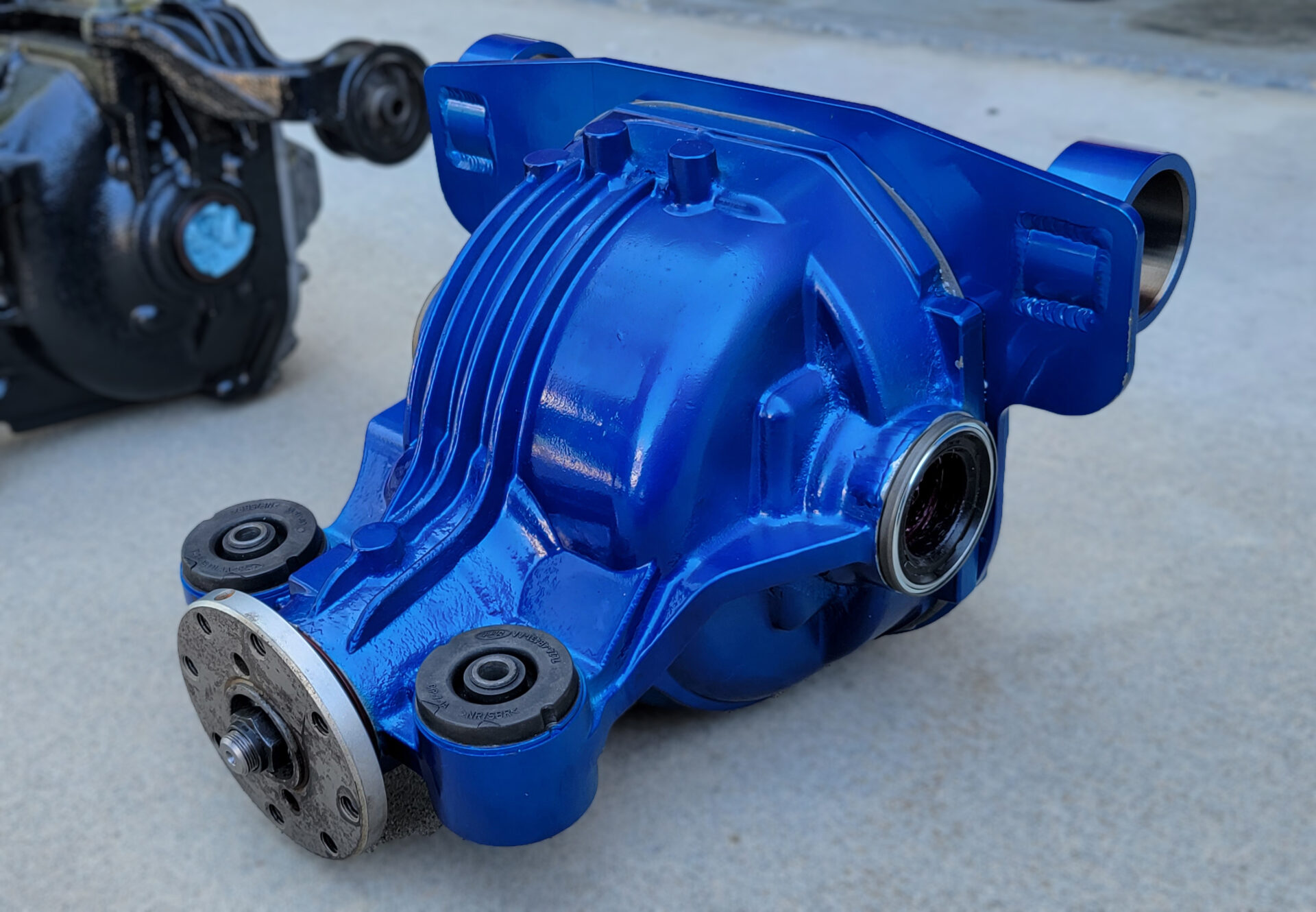
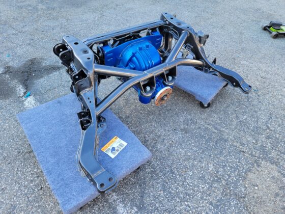
 With the masking tape removed, we allowed the housing to cure.
 We also painted the rear diff mount to match the rest of the differential.
 We used SuperPro Polyurethane Bushings for the rear mount of the differential. These bushings were the same size as the bushings for the OEM FD RX-7 diff. SuperPro poly bushings strike a great balance of reducing movement without affecting Noise, Vibration, and Harshness.
 We turned our attention to the Ring and Pinion. Choosing a gear ratio is very important, and it greatly affects everything from freeway cruising RPM and fuel mileage, to straight line acceleration, how often and when you shift on a race track, and it can greatly affect lap times. Selecting an ideal gear ratio takes a lot of things into consideration from tire size, transmission ratios, redline, the engine powerband, and even the speeds in canyons or corners of specific race tracks.
After running multiple calculations, we decided for our raised redline target of 9,000rpm, the stock transmission gear ratios, and the direction of upgrading the transmission in the future, we settled on a 4.30 to 1 final drive ratio.
 The stock pinion gear has a few sharp edges and stress risers, as well as a very basic chamfering of the edges.


19 comments
Looks like a win-win upgrade (adding a clutch-type LSD, reducing the assembly’s weight, and improving durability). Really enjoying this project – thanks for sharing all the progress!
It isn’t a clutch LSD. He literally describes it as a gear LSD.
Facepalm. Not good reading comprehension on my part. Thanks for clarifying.
It’s always great to hear Mario’s named mentioned from TSR. He’s an artist with a welder. I love all the work he has done for the Datsun community.
This thing will be a monster! I appreciate all the updates.
Awesome to see the attention to detail on the ring and pinion gears! All that work will increase the fatigue life by magnitudes.
Love it. I’m still waiting to see a brake rotor WPC treated to see how much longer the brake distances would be.
Whats the difference in length, axle centre to driveshaft flange between the two diffs? Currently have an aftermarket clutch type diff in the OEM housing that I don’t really trust behind a T56 Magnum. It’d be a shame to bin/remake the carbon driveshaft shaft…….they look pretty close!
The Ford Explorer 8.8″ diff flange (using the Ronin mount) is 0.425″ rearward/closer to the axle centerline than stock. It sounds like your best bet is to get a 0.425″ spacer to adapt your driveshaft to the Ford 8.8 diff flange.
Perfect – thanks Billy. That’s better than trying to go the other way! Looking forward to your next instalment.
While the out side of the assembly might be larger, it’s no guarantee of greater strength. A measurement of the gears and the bearings would be needed to make that claim. The fact the Ford unit is lighter is also a factor. Also the original mounting with the PPF is quite strong, as the lever arm of the PPF is much longer than the bushings located right at the companion flange.
Size does not determine strength, but the 8.8″ Ford gear and aluminum diff housing are known quantities to handle over 1,000hp. The FD’s PPF and cast iron diff housing are also known quantities and known to be weak and unreliable in the 400-450whp range.
Hi there can sombody tell me which model Eaton Detroit Truetrac LSD was used please?
Eaton Part number please?
Many thanks
ETN-913A561
What brand and weight gear oil is recommended for the Ford 8.8 differential? This would be for FD RX-7 Drift Car, thanks!
It depends on what limited slip differential you are using. For the Eaton/Detroit TrueTrac, it is crucial to use a conventional, NON-synthetic gear oil with NO friction modifiers. Lucas Heavy Duty High Performance 80W-90 Gear Oil, and Torco RGO Racing Gear Oil 80W-90 are good options that fit these requirements.
What brand 4.30 Ring and Pinion were used on this build?
Motive Gear F888430 Ring & Pinion Set, Ford 8.8″ Standard, 4.30 Ratio, 30-Spline, 10-Bolt, 8620 Steel, Compatible with F-150, Mustang, Explorer, Crown Victoria, Ranger, Lincoln, Mercury (1980-2020)
Then once the CD009 transmission was chosen, it was changed to:
Ford Racing M420988355 8.8″ 3.55 Ring and Pinion
We appreciate the build details, and for the reply. Starting to gather parts for our own build, thanks to you all.