,
 |
| Romex NM-B is a non-waterproof electical cable that can be used indoors. If you require outdoor use, the UFB cable is the same but has a stronger jacket to withstand the elements. |
Nonmetallic cables are labeled by gauge and number of wires. The gauge signifies the wire’s electrical current load limits. Too small a wire will become hot and could ignite. 12/2 wire will complete this garage project. The first number indicates wire gauge while the second indicates the number of conductors in the wire. 12/2 signifies 2 insulated 12 gauge wires, plus a bare copper grounding wire. A 12 gauge wire has a maximum rating of 20 amp, 120 volt capacity and use. 12/3 wire has 3 insulated wires, and is used for outlets that can be turned on and off with a switch. Run the wire through the wall supports or above the ceiling to where the other outlets will be. In this case, drilling through every 2×4 wasn’t inviting.
 |
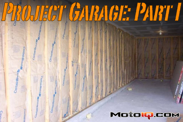
| Luckily, the space above the garage was easily accessed and like an attic, running wire through that space made the job much easier. There was already a hole for the wires connected to the existing outlet so up the ladder went the 250′ of 12/2, more than needed, but cheaper by buying bulk and no doubt it will all be used eventually. |
Drill holes in the wood above where you want additional outlets. Two extra holes were drilled along the garage ceiling for the additional outlets. Fish the wire down the existing hole and have another person pull it long enough to connect to the outlet.
 |  |
If the drill bit isn’t long enough to go all the way through, pound in a long screw or nail into the partially formed hole from the garage and keep your fingers crossed that it pierces the space above the ceiling to know where to finish the hole off. | Just to be safe, it should be about 8-12″ longer than where it goes through the receptacle box. |
Run the wire in the attic to the next hole. If this is a middle outlet, instead of cutting the wire and running it twice down the hole for the input and output, push it down in a U-shape until you have the extra wire below the outlet for each side of the wire. The last outlet will only need the wire to reach it, not return back.
 |
| Connecting the wires backwards will result in reverse polarity. Turning the switch off would turn off the neutral wire, not the live wire, and could result in buzzing radios, humming lights, or involuntary shock therapy. |
The outlets being installed are screw terminals. There are push in fittings available as well but screw terminals are the easiest and most popular. Nail or screw in the outlet boxes to the 2×4 wall supports. Use a cable ripper to cut the plastic sheathing from the individual wires (or some pliers and the ability to not cut the wires in the process). Strip away the insulation on the individual wires about 1-2 inches. Using needle-nose pliers, form a little C shaped loop on each wire and hook the wires around the screw terminals forming a clockwise loop (right side should come up from the bottom, left side down from the top). Double outlets have one grounding screw, two silver screws, and two gold screws. The hot wires should connect to the gold screws, neutrals to the silver ones. The green screw is for the grounding wire. Since there will be other outlets running off this one, a grounding pigtail must be used to connect the grounding wires to the one green screw. A grounding pigtail has green insulation and is available with a pre-attached grounding wire that connects to the electrical box. Use needle-nose pliers to twist the two grounding copper wires together and then use a wire nut to connect the pigtail wire to the bare copper grounding wires. The grounding screw connects to the grounded metal electrical box.
 |
| I will not be connecting all the outlets to the wires until after insulation and drywall is complete. If this is the case, roll the wires up and position them far back in the box for now. |
House receptacles are typically rated between 110 and 125 volts. To give the option of higher powered tools like a hefty air compressor, a 220 volt line was also wired in next to the first outlet. The 220 line uses 6/2 wire, or two 6 gauge wires and has a 60amp, 240 volt capacity and use. The wire was inserted through the same hole as the others and connected to a separate outlet. The rest was left in the garage attic to be completed when necessary. Outlet receptacles will be installed after the insulation, drywall, and painting are done.