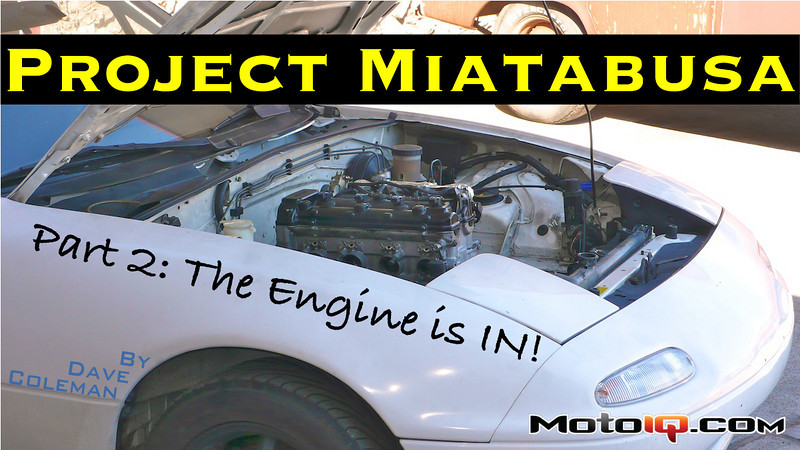
Project Miatabusa – Part 2: The Engine Is IN!
by Dave Coleman
A few short months ago, when we introduced project Miatabusa, (part 1 is here) it was little more than a reasonably well thought out concept. We had measured some things, made a rough SolidWorks model of what we thought a Hayabusa engine mated to a Miata transmission might look like, and confidently put our Miata's original engine on Craigslist. We had a plan, but in all honesty, it still didn't seem that real.
Well kids, we've cut metal and bolted an actual Hayabusa engine to our transmission using an actual billet adaptor plate. This shit is officially real. Before the back-slapping begins, lets step back and look at the concept again.
 |
||
The idea of using the Hayabusa's built-in 6-speed sequential dogbox was rejected early on. Experience has shown that bike transmissions wear out too quickly when subjected to car-sized loads. Experience has also shown that not having reverse is less convenient in a car than it is on a bike.
Bolting a Miata flywheel to the Hayabusa's crank was also rejected. Not only is the 11,000-rpm powerband a poor match for the Miata's gearbox, but the crank doesn't have any provisions for anything as big as a flywheel on the end. Both ends of the crank are small, like the front of a car crankshaft.
Like nearly all motorcycles, power transfer from the crank to the gearbox is through a big gear, and in the Hayabusa's case, the gear reduces speed (and multiplies torque) by a factor of 1.596:1. This is where the Hayabusa's clutch resides, and this is where we decided to put our flywheel–on what was once the bike transmission's input shaft.
This solution keeps the maximum revs coming into the Miata transmission down to a very manageable 6900 rpm, virtually identical to the engine it was designed to support. This should keep flywheels from exploding, synchros from protesting, and powerbands from being horribly out of step with the needs of a car.
Starting with this assumption, we made a rough SolidWorks model of the Hayabusa engine, with a Miata bellhousing pattern centered on the Hayabusa's clutch shaft. After a few measurements, it became clear that this layout posed a problem. The Miata's steering rack went right through the Hayabusa's sump. Not cool.
Rev B. solved these problems by rotating the engine so the offending portion of the sump sits above the rack, and ditching the compact Hayabusa starter, which sadly has a not-so-compact gear drive that pushed the engine an inch and a half farther forward than otherwise necessary. The plan, at this point, was to use the Miata starter to spin the miata flywheel (a task for which it is uniquely suited).
 |
 |
|
| Our original concept looked roughly like this, with the engine leaned toward the passenger's side at the same angle it normally leans (to the front) in the bike. Rotating the engine until it was vertical helped clear the steering rack. | The perspective in this view is different, but the flat section on top of the green bellhousing plate will be horizontal in the car. The big pink gear is the power takeoff gear. The yellow structure behind that is an adaptor that bolts to the clutch cover mount, and the green plate mates to the bellhousing. |
Removing the Hayabusa starter's gear reduction box exposed the back of the crank. We had to seal it back up to keep oil from gushing out the hole, so we took the opportunity to solve two problems at once. Our new design is in two pieces. The first piece, which replaces the Hayabusa's clutch cover, will hold a giant double-row ball bearing that supports a flywheel shaft and the big power takeoff gear. Behind that, we'll bolt up a bellhousing adaptor plate.
The clutch cover wasn't load bearing, though, so it was held on with tiny, 6mm bolts, and the bosses those bolts thread into are thin and delicate. In its new role as a car engine, this flange has to withstand not only the torque reaction forces from the engine's output, but also some substantial bending loads from the weight of the transmission. To help address this, we decided to use the bellhousing plate to cover that gaping hole at the nose of the crank. This second ring of bolts (and a few alignment dowels) well offset from the flywheel centerline will help take those torque reaction forces.
Theories and solid models are fun and all, but the real sexy stuff comes when you start smelling cutting oil. Turn the page, hit the jump, click on the tiny little “next page” down there, and take a look at how it all works out.


1 comment
I really want to build a haybausa rock crawler. I see that you made a adapter to the miada transmission. Would you sell the cad files or the adapter for me to make this combo work? I want to copy this exact build so i can make a small moon buggy for the rocks. Any help would be appreciated. Thanks