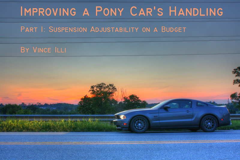

Project Mustang 5.0 Part 3: Optimizing Weight Transfer and Roll Steer
By Vince Illi
In the last installment, we tightened down Project Mustang 5.0's chassis with Whiteline sway bars and strut bracing, dramatically increasing its tarmac-holding capability and making the chassis much less prone to being “upset” in quick transitions such as slaloms.
Now, we're going to turn to the rear suspension. All suspension configurations are compromises. The engineers who design them have various objectives and must make compromises within a Trade Space to satisfy as many of those objectives as possible while working within constraints such as space, comfort, performance, and budget.
The S197 Mustang has a rear suspension configuration known as a Three-Link with Panhard Bar. A diagram of this suspension is illustrated below. Three-link suspensions are one of the most widely used geometries for solid axles with coil springs.
 |
| Dang it, Jim! I'm an Electrical Engineer, not a draftsman! |
The three-link suspension uses three Trailing Arms (also known as “control arms”). Two of these trailing arms are attached to the bottom of the axle directly adjacent to the wheels. We'll call these the Lower Control Arms, or LCAs. The third link is attached to the center of the axle, directly on top of the differential. This is the Upper Control Arm, or UCA. The purpose of the trailing arms is to locate the axle longitudinally (or front-to-back) on the chassis. As the vehicle traverses bumps and goes around corners (causing weight transfer), the axle pivots on the trailing arms, but it does not move longitudinally relative to the chassis except in the arc defined by the trailing arms.
Although it is called a “three-link,” there is a fourth component of this system: the Panhard Rod. As I said previously, the trailing arms locate the axle longitudinally, but they don't do a very good job of locating it laterally (or left-to-right). The panhard rod can be thought of as another trailing arm, but one attached in an axis perpendicular to the others. On the Mustang, the panhard rod attaches to the axle directly adjacent to the driver-side wheel and to the chassis near the passenger-side wheel. The panhard rod prevents lateral movement as the car traverses bumps and goes around corners.
 |
| I'd like to think my drafting skills are improving, but we all know they're not. Note that these diagrams are not to scale. |
Looking at the axle from the side and ignoring the panhard rod for a moment, we see that the rear axle rotates around these control arms as the suspension compresses and decompresses. The axle does not move perfectly up and down. If we draw an imaginary line from the UCA and LCAs, the point of intersection is the Instant Center. This is the point about which the axle rotates as the suspension moves. The instant center changes location depending upon where the suspension is in its travel; it is not constant.
 |
| The Instant Center is defined (from the side) as the intersection of imaginary lines drawn through the upper and lower control arms. (Not to scale.) |
You can see that the axle travels in an arc as the suspension moves. This arc is defined by both trailing arms, but primarily by the longer, lower ones. Because of this, the angle of the LCAs relative to the chassis dramatically affects the handling characteristics of the vehicle. This angle affects a vehicle's cornering, braking, and acceleration.
The lower control arm angle affects straight-line performance first and foremost. This is why drag racers often swap out the stock LCAs as one of their first modifications for making their car “stick” during a hard launch. To understand why, let's think about what happens when the Mustang accelerates hard from a stop (or coming out of a corner).
Looking at the diagram above, we see the axle, wheel, and control arms from the driver's side of the car. When accelerating, the wheel is turning counter-clockwise. Due to Newton's Third Law, the axle tube is thus trying to turn in the opposite direction, or clockwise.
The OEM attachment points for the control arms are via bolts and rubber bushings. Those rubber bushings, while great for a comfortable ride, deform when the forces of hard acceleration are applied to them. This creates slop, or “binding,” which leads to wheel-hop and less-than-ideal acceleration. Furthermore, the stock control arms are simply made of stamped steel, which is not the most rigid design. Therefore, the first step to upgrading the control arms is to replace the bushings with stiffer ones (or rod ends if you're hard-core) and replace the arms themselves with a more rigid design.
Ignoring the bushings for a moment, you can see that the axle tube “pushes” the car forward via those lower control arms. This is where the angle of those LCAs comes into play. From the factory, the lower control arms are parallel to the ground. During hard acceleration, that control arm also “pushes” the car forward parallel to the ground. There is also a tendency for the control arm to rotate upwards around its front mounting point, moving the axle upwards relative to the chassis and contributing to “squatting,” or rearward weight transfer.
But what happens if that lower control arm angle changes?