
 We installed the WHP Wideband Knock Sensor kit from ECU Master. This kit features the wideband knock sensor, connector, pins, and terminals, and a M12x1.25 titanium mounting stud. These wideband sensors take advantage of the sophisticated knock detection circuits in modern ECUs like our Motec M150.
For years, knock sensors were designed to generate an output voltage only around a preset frequency. This prevents the ability to separate knock from noise. With modern ECUs, wideband knock signals can be processed throughout the entire frequency range, and can be programmed to only look for sounds that actually represent knock. Knock signals can also be filtered by crank degrees so it only monitors the sensors at engine positions where knock is likely to occur.
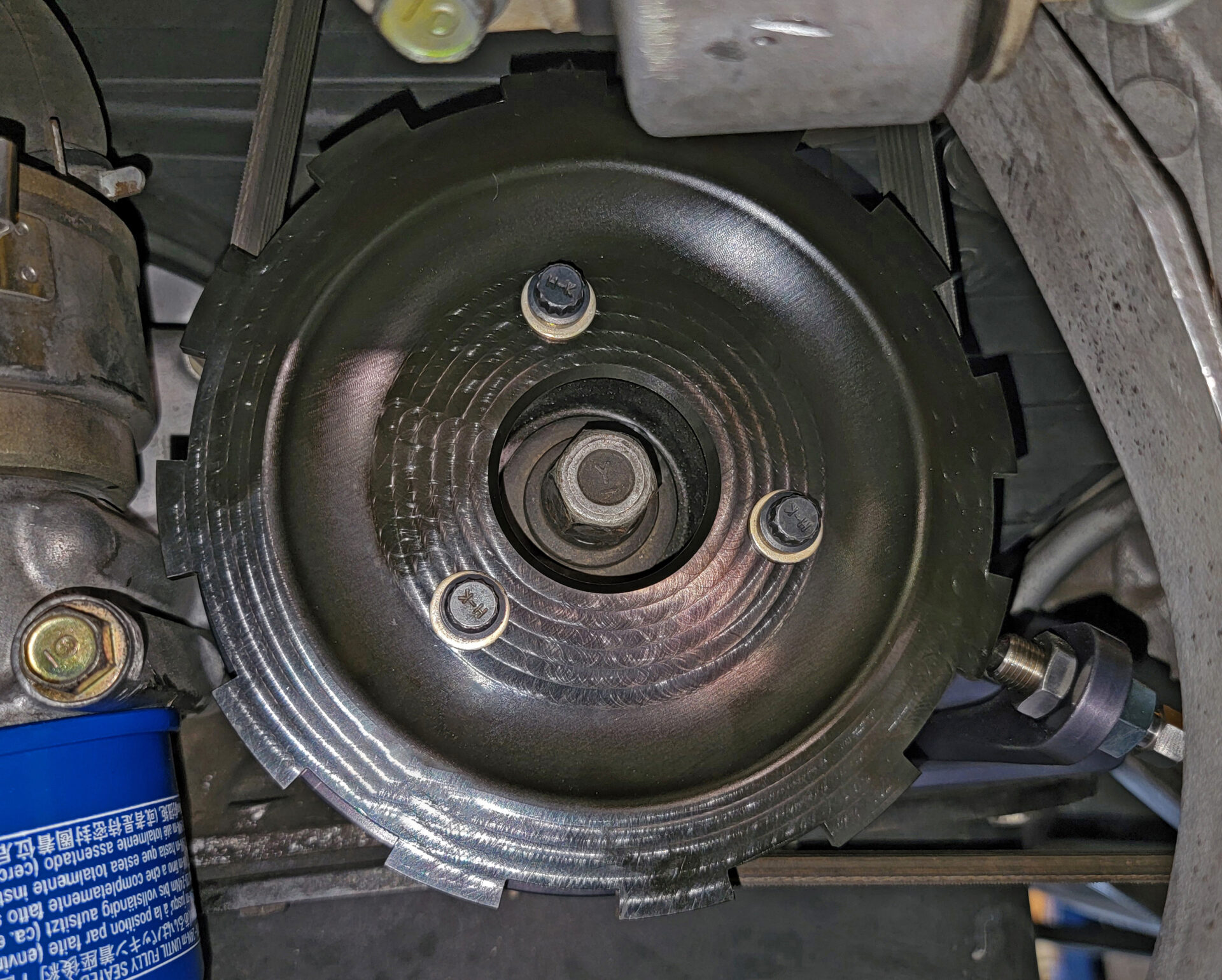
 We clocked the sensors to clear the intake manifold, which required us to remove the VVIS plate to provide additional clearance for the knock sensors. From our testing, reducing the volume of the intake manifold had very little effect to the power of the engine, and the benefits of the wideband knock sensors greatly outweighed the loss in plenum volume.
 We wired the wideband knock sensors to the factory harness, but the sensitivity of the sensors required an additional ground to the ECU directly. We tapped one of the ground wires in our sensor harness for this ground.
With our new custom-designed tone wheel, hall effect crank position sensor, and WHP Wideband Knock Sensors installed, we set up the parameters in the M150 and now have substantially more resolution, data, and control over our NSX’s C30A engine which will be crucial when the turbo motor goes in.
For more information on the Crank Position Sensor and Tone Wheel, contact HQ Engineering.
8 comments
Back in my OEM engine calibration days, we referred to the time period where knock is likely to occur as the gate period. This can be determined by the crank angle and firing order. Knock should only typically occur during a small range of crank rotation for any given cylinder. We utilized 4 and 8 channel oscilloscopes to view and measure the raw knock sensor output signal, and then match it up against what we heard. A good microphone and a quality set of headphones go a long way. If a ‘knock’ waveform was detected for a particular cylinder, but was outside the gate period, it was largely ignored. We also calibrated the ECU to ignore these signals so it does not interfere with the knock control learning logic. Knock control system calibration on a modern Japanese V8 engine with 4 knock sensors could take 4-6 months. So basically, you’d run the engine at medium to high loads, advance the timing till a determined level of knock was achieved, and then analyze the data. After 4-6 months of knock testing, we’d do a HP check, confirm numbers, and then disassemble/inspect the engine. It was usually one of the last calibrations performed as any mechanical change or addition to the engine would change the harmonics, and require re-testing.
FYI, most OEM engines are calibrated to run at a certain/safe level of knock. It’s perfectly fine in most situations. You’d be surprised at how durable most engines are… well the one’s I worked on anyway. 🙂
Very interesting!
I also have some past excursions in engine dev; we supplemented knock sensors with individual cylinder pressure sensors (also with an O-scope during dev). These were big engines though, and I think I remember the pressure sensors were a permanent part of the control system feedback in the same way as the knock sensors. Crank angle gating is definitely a normal part of knock strategy.
We used Kistler combustion chamber pressure measurement sensors as part of the testing as well.
You definitely didn’t work on Subaru EJ’s then (in reference to durability) lol
These are the articles I hope to see anytime I click on MotoIQ, Thanks!!
Hey one of the best project Supra articles has the wrong pictures in it- it’s an article about the cylinder head, but with all bodywork photos!!!
Mike I also wanted your opinion on Bosch 4.9 wide band sensor placement in a turbocharged 4-500 horse flex fuel engine-
Thanks guys sorry not fully on topic
I would say put it in the collector.
Nice work!