,
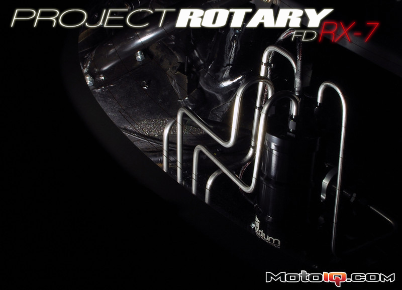
Now that the main components are installed we can focus on the insane amount of plumbing that a setup like this requires. Everything used for this build that is not hose is 3/8″ double annealed, smooth bore 304 stainless tubing with 37-degree flared ends. One big factor to consider when ordering stainless tubing is to make sure that it is double annealed. This will ensure than it is easy to bend and flare. It also reduces the risk of cracking the tube while flaring.

Factory 5/16″ plated steel tubing next to the new 3/8″ double annealed 304 stainless tubing. Notice the difference in internal cross-sectional area. Feel free to ignore the factory fuel pump that was used as a prop.
The factory fuel system uses 0.030″ wall, 5/16″ OD steel tubing. People have put down over 500 horsepower to the ground out of RX-7's with the factory fuel tubing, but this is far from ideal. As an quick example (don't worry I'll spare you all the boring calculations), if a RX-7 requires 340 L/hr of fuel at the injectors and it is getting this fuel through the factory tubing from the fuel tank (~12 feet from the tank to the rails), there is a pressure drop of approximately 7.6 psi due purely to the size and length of the tubing. This means that to run 40 psi fuel pressure at the engine, the fuel pump will need to run at 47.6 psi (unrealistically assuming no other losses). By running the pump at higher pressures its efficiency decreases and it isn't capable of supplying as much fuel. It also adds heat to the fuel and increases the electrical current draw of the pump.
Now take the tubing that we are using in this build, which is 0.028″ wall, 3/8″ OD tubing. This size tubing has an internal cross-sectional area 55% larger than the factory 5/16″ tubing even though it only has a 1/16″ larger outside diameter. What this extra area means is that given the same 340 L/hr flow rate the 3/8″ tubing will only have a pressure drop of 2.7 psi, which translates into increased pump capacity, cooler fuel temps, and less strain on the alternator. Now this may not seem like a big difference, but once all the connections and bends are accounted for in the pressure loss calculations the improvement is nothing short of staggering.
With that short engineering lesson over, we can start building tubes.

All tubing is bent with a Parker bending tool that is dedicated to bending 3/8″ tubing. Using a tool like this allows bends up to 180-degrees and makes bending stainless tubing easy due to its long handles and hex base for clamping in the vise. The tool features a 15/16″ bend radius (CLR) which is about as tight as you want for 3/8″ stainless. Since the wall thickness of this tubing is slightly less than what is recommended by the tool manufacturer, a small amount a flattening does occur in the bend.

Stainless steel tubing should not be cut with a standard circular bladed tube cutter. These types of cutters work-harden the tube at the cut which can cause one of two problems, either the tube will be extremely difficult to flare (potentially damaging the flare tool) or the tubing will crack and split, rendering the painstakingly bent tube scrap metal. To prevent any problems, all tubes are cut with a fine tooth hacksaw then hand filed inside and out to give clean edges for the flaring tool to work with.

Flaring stainless tubes should be done with a flaring tool designed to work with stainless. Some cheaper tools may work for a few flares, but can wear out quickly. Also, picking a tool that flares at the correct angle is important. AN and JIC fittings use a 37-degree flare, while many other fittings use 45-degree flares. Pictured here is the Ridgid 377 37-degree flaring tool that was used to flare the 20 tube ends that exist in this fuel system. It's also worth mentioning that it's important to remember to put the tube nut and sleeve on the tube prior to flaring or you'll be kicking yourself.

Close-up picture of a flared tube end.

Sometimes you have to take a mulligan and try again. Here is a picture of the final good tube assembly next to one that was scrapped. The bend line was off by just enough to make it unusable.