,
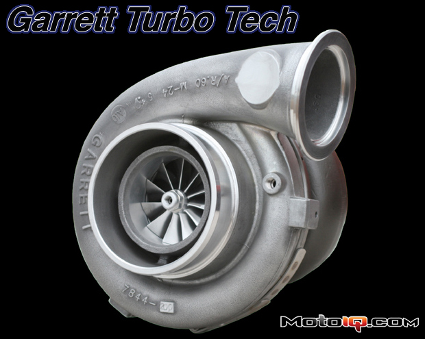
All these things affect the shape and number of blades. The blade configurations seen include the 6-full/6-splitter arrangement that is commonly seen on aftermarket sized turbos, along with 5/5 and 7/7 configurations. For something even more unique, the Garrett Dual Boost uses a double sided compressor wheel!
 |
| Garrett's dual boost twin sided compressor turbo has the pressure ratio range of a staged turbo system but packages like a conventional turbo system. |
Though only now being seen with the GTX in an aftermarket application, the use of only full blades has been used previously in OE applications. Each configuration of blades has its positives and negatives related to flow rate, efficiency, and even noise. As for the blade shape itself, there are an infinite number of variations; it’d be like comparing all the aerodynamic appendages attached to the different Formula 1 cars. Every one is different.
 |
| If we are talking about compressor maps, we should explain what we are talking about. |
 |
| This map shows the differences in flow and map width between mid frame turbos, the old school TO4 family, the newer GT4294 and the GTX4294. This clearly shows that the GTX turbo is the hands down winner with no drawbacks: more surge margin considering the additional width of the map, extended operation into the higher pressure ratios and much higher flow. |
With the basic performance requirements, the wheel can be designed. The flow and map width targets are important because they will determine the diameter and trim of the wheel. The shape of the hub is also important as it controls the air as it passes through the wheel; it is similar to not wanting a big angle or jumps in angle in a nozzle or diffuser. CFD is used in each step along the way and predictive compressor maps can actually be generated! All compressor wheels are generally designed to about the same maximum tip speed; so the bigger wheels will have a lower maximum rpm. Looking at the compressor map for a GTX4294R, the top speed line is 118k rpms. The GTX3071R compressor map shows a top speed line of 150k rpms. Smaller compressor wheels spin to well over 200k rpms!
 |
| The top speed of the mid size GTX3071R zings along at 150,000 RPM. Small frame T25 turbos can spin up to 250,000 RPM! The top speed line can be found at the top of the map. |
.
 |
| Conversely, the bigger GTX4294R spins at a much slower 118,000 RPM. This “slow” RPM is nearly unfathomably fast, so you can imagine the amount of stress a compressor wheel has to withstand just from spinning! |
Let’s stop here for a second and say that a wheel's geometry has been designed that meets all the performance targets. Is the design complete? Not even close. A great performing wheel is of no use if it does not hold together. Compressor wheels encounter tremendous stresses involving both pure mechanical stresses and also cyclic related stresses. The frequency related stresses can be categorized into Low Cycle Fatigue (LCF) and High Cycle Fatigue (HCF).
LCF is from repeated acceleration and deceleration of the turbo speed such as on city buses that are driving in a stop-and-go cycle; imagine going from 5k rpms to 100k rpms and back down to 5k rpms every 10 seconds. This creates immense stress on the wheel.
HCF is related to objects within the turbocharger itself that cause the blades to vibrate as they pass by the object. For example, each rib that supports the ported shroud will excite the blade as the blade passes by it.
 |
| The changes in air resistance in a nanosecond caused by the compressor blade tips passing the ribs supporting the center section of a ported compressor housing causes cyclical stress that can harmonically add up to the point of damaging a compressor wheel if it is not properly designed. |


