,

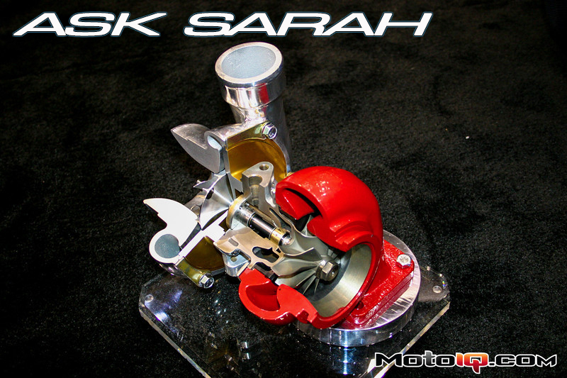
Computer aided design programs (CAD) and fluid dynamics analysis make designing for maximum efficiency almost easy, on paper at least. Programs calculate optimal blade shape and angle and wheel mass. Turbine wheel efficiency is a product of the turbine housing A/R sizing and compressor wheel diameter. The turbine side can be altered for an optimal speed to keep up the velocity of gas flowing through it. The compressor wheel diameter can be modified to increase or decrease the mass flow of air it can push for a given compressor speed. These are the PB&J of a turbocharger. Modifying the size of the wheels changes the blade speed ratio (U/Co, or blade tip speed divided by speed of gas flow into the turbine wheel), which affects turbine efficiency and the turbo’s responsiveness. By using software to generate predictive turbo maps, turbo efficiencies can be optimized on paper before they are ever put into production. Of course, even when the perfect turbo design exists on a computer monitor, finding a way to manufacture it can be difficult.
“Shank” Design
There are an infinite number of blade configurations from full blade to splitter design. Computer modeling has also been essential for blade stress analysis. Turbine wheels should be designed with most of their weight as close to the axis of rotation in order to accelerate quickly and not break. If the blade tip is located further from the hub, it has a longer leverage arm. Keeping this blade strong will require a thicker (beefier) blade. Exposing the blades to each order of harmonics (usually up to the 7th order) will expose their stress points. Once the blade self-destructs, the engine can ingest aluminum shrapnel- an “oh shit” moment for many turbo owners. Both LCF and HCF (Low and High Cycle) fatigue stresses are tested. LCF tests stop and go (city) driving while HCF is more related to the internal pieces of the turbo and the vibrations they create or incur. Computerized testing can narrow down what's worth putting through the rigors in real life.
Spool up!
The Variable Nozzle Turbine (VNT; Garrett or Honeywell) or Variable Geometry Turbine (VGT; Cummins/Holset) or VTG (BorgWarner, ABB), or VGS (IHI) among other similar acryonyms uses an actuator to adjust a row of movable vanes near the inlet of the turbine wheel that can control exhaust flow to the turbine blades. The angle is adjusted to optimize performance for the engine’s large rpm operating range. At lower engine speeds, the vanes narrow the passage the exhaust gas flows to make the turbine blades spin faster, letting it spool quickly like a small turbo. At high engine speeds, the vanes are fully open focusing the exhaust flow directly to the turbine blades. VGT technology has been used in turbodiesel engines for 20 years but gas engines run much higher EGT’s and most VGT turbos couldn’t endure the heat. The Porsche 911 Type 997 B50 turbo was the first gasoline turbocharged car to use this type of turbo only after some innovative aerospace materials that were capable of the high engine temps were used in the fabrication. Outta this world!
 The Chevy Cruze engine uses a single pneumatically activated Garrett VNT turbo. It produces 21psi under wide open throttle but can get up to 23psi during an overboost situation like needing a quick boost to get ahead of the traffic.
Garrett is also developing axial turbine technology (typically used for aerospace) with a dual-sided compressor. Most turbos feature radial turbines. Air flows in vertically, changes direction, and exits horizontally. With axial turbines, air flows in horizontally and exits horizontally. Axial turbines can be smaller in size (better for packaging) but can deliver the same flow, reducing inertia by a third to improve throttle response. They spool and respond like their smaller counterparts but flows like a larger turbo.

Future of Turbos
Given the ever-increasing fuel efficiency requirements along with our quest for more power, the future is headed even more into the turbo realm with boosted hybrid engines likely to be present in the majority of cars on the road within the next few decades. This will require more enhanced wheel and housing designs that can function with hybrid technology (limited oil on restarts: ball bearing center sections, and quick increases in temperature) and more advancements in assisted turbocharging (using an electric or hydraulic motor or other F/I device to compliment a turbo) as well as computer aided modeling and materials/casting improvements. Turbos will be more aerodynamic, efficient, and reliable. After all, we’d still be watching 2.4L naturally aspirated V8’s on the F1 circuit instead of this year’s 1.6L V6 engines with turbos and energy recovery systems if it weren’t for designs intended to push development in passenger cars that reduce both fuel consumption and emissions. Yes, F1 had a turbo era that last ended in 1988 but even if it doesn't pan out for good, the technology developed for the next few seasons will still cultivate turbo performance in the real world. Get Boosted or Suck!
Got a difficult tech question? Email Sarah at asksarah@motoiq.com


