


Nowadays Race Car and dual-purpose Street/Track day aerodynamics are a hot topic with car enthusiasts. The wild aero on time attack car and the time attack style aero kits that are coming on the market are getting a lot of attention. However, when applying aero to your own car there are a lot of things to keep in mind. The first being that aero is not intuitive and what works well on a factory LMGT car that has been designed using CFD and tweaked in a wind tunnel then perfected via physical testing can’t simply be grafted onto your daily driver with the same sort of results.
In fact without analytical tools, some knowledge of fluid dynamics and some time and budget for testing, it is really easy to go backward when it comes to aero. The most common mistake is tacking all sorts of appendages you saw on a DTM, LMGT or Unlimited Class time attack racer and perhaps making decent downforce but with a huge penalty in drag with a loss of speed and higher lap times because you didn’t balance downforce to drag considering your power level. If you are building a high powered decently budgeted racer, perhaps your best bang for the buck is going to be in hiring a professional motorsports aerodynamicist, this way you are going to get something that has a high probability of working.
Now most of us can’t afford to hire an Aerodynamicist and wild experimenting can go sideways easily so I am going to show you a few simple easy aero things that are guaranteed to work and not too hard to make. These easy and basic aero tips will not go backward and will not have a severe drag penalty.

The first part of easy aero that any grassroots racer can do is a splitter. A splitter can create a significant amount of downforce with a minimal drag penalty. It is also super easy to make. A splitter is a horizontal aero device that is on the bottom of the front of the car that juts forward. When air hits the front of the car, it decelerates and by Bernoulli’s principal, gives up velocity to make pressure, engineers call this stagnation pressure. What a splitter does is to trap the stagnation pressure at the very front of the car to give it a downward component due to the pressure differential between the top of the splitter and the bottom.
Depending on the shape of the front of the car and the configuration of the splitter, a splitter can make anywhere from a hundred pounds to even over a thousand pounds of downforce! A car with a long nose with a flat front can make a lot of downforce with a splitter. A car with a short overhang and a rounded profile in plain view with a sleek pointed front does not work as well with a conventional splitter
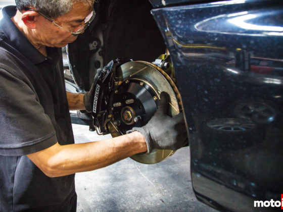
A splitter just needs to be flat and stiff, it has to take a load of several hundred pounds without bending or breaking off. On this race car, the Dog II which is a sexy Nissan B14 Sentra the splitter is a laminate of aircraft grade spruce, epoxy resin, and carbon fiber made by Brian Kono of Afterhours Automotive. This was done to save weight and let’s face it, to look cool. You can make a fine splitter of 3/4″ plywood. I have and painted them with a sealer then truck bed liner paint or even sealer and a couple of coats of semigloss latex house paint with a roller! The main thing is to remember to make your mount strong enough, direct to the chassis is the way to go and even a small splitter should be able to take the weight of a person without breaking.
In order to work, a splitter has to be at least within 4″ of the ground. Closer is better, however too close isn’t good either, if you have underbody aero like a diffuser, if the front of the splitter gets so close to the ground, for instance when hitting bumps or when the nose of the car is diving under braking, the flow can get suddenly cut off rendering the underbody aero ineffective. This can cause a sudden loss of traction. This phenomenon is called pitch sensitivity.
Although even a small subtle splitter can make a big difference, bigger can be better. A general rule of thumb is that the biggest gains are seen on splitters up to 4″ in length and from there longer is a matter of diminishing returns. You can usually see this in CFD representations of cars, the zone of highest pressure in the front of the car, is usually only a few inches past the front of the car.
On our car, NASA rules at the time limited the splitter size to 4″ past the attachment point and this bumper is just that. In other classes, the splitter can only be as long as the outer profile of any OEM body panels. One reason why we stuck to 4″ is that any longer and the car would require removal of the splitter to load on the trailer and we were lazy!

For a splitter to work best, you need a belly pan. The splitter will help create a pressure differential over the entire length of the splitter/belly pan assembly creating more downforce. In the case of our car, NASA rules at the time limited the belly pan length to the front of the front wheel opening. Ideally, you want it as long as possible, heck a whole flat bottom is best but for your typical grassroots garage fabrication, perhaps to where the lower control arms mount is practical.
One thing to remember is that the splitter/belly pan can block access points for maintenance, repair, and transportation so it helps if the mounts can be easy to access and removable. This makes your aero less of a pain in the ass. On our car, the splitter/belly pan has bracket mounted pins that slide into holes on the support bracket mounted on the frame. The belly pan splitter can be removed in seconds.

8 comments
You mentioned “racket mounted pins that slide into holes on the support bracket mounted on the frame. ” Any chance you have a part number or example link to go off of? Thanks!
The pins were just something we made.
Ive got A Z32 Race/Street setup. Still using the factory locations for the intercoolers (using US spec bumper). Would it be best to have the air exit out the bottom if front of each wheel or put vents in the wheel wells? Currently I am only using the factory exit out the bottom ( the version without the factory NACA duct).
Rear Diffusers in the back are challenging due to the dual exhaust. At this time I am not interested in a side exhaust. How much would it reduce in performance if you ” poke” the exhaust through or would I be better off making a smaller one that just goes between both exhaust pipes?
Last thought. It’s regarding air flow in the Engine bay. Currently I don’t have any holes in the hood, however I was thinking of taking off the molding that seals the hood near the windshield/wiper area. It would leave a 1″ gap along the entire width of the hood where the air could exit. I am unsure if that would help or hurt.
I would vent in the wheel well or better out the sides in front of the wheels. It is better to blow the exhaust over the top of the diffuser rather than in it. Removing the molding at the rear of the windshield is a bad idea, the base of the windshield is a big high-pressure zone, the flow would back into the engine compartment, the opposite of what you want.
By your comment of the high pressure zone in front of the windshield, would that also mean lifting the hood to vent hot air is a bad idea/ineffective?
Yes, looks cool, works bad. Look at static pressure contour from CFD on Google image search. Pretty obvious, it’s a bad spot to vent. You want to vent in LP zones, gurney flaps, and gills, can prevent flow reversion.
Those strakes on the diffuser are flow conditioners, not VG. The point of them is to reduce spanwise flow. They were heavily used on early swept wing aircraft.
Also, the point of producing a vortex, is to have an effect on a surface downstream, pointless to put VG on the rear, unless that vortex is directly making down force (which is unlikely, but not necessarily inconceivable.)
I disagree and so do other motorsport aero guys including the guy who helps me that has a PHD in fluids.