,

The stock filler neck is hacked up for use with the new fuel cell.
We wanted to keep the factory filler location as mentioned in the first installment. Since the factory filler also comes with a nice cap and mounting assembly, we tried to reuse as much as we could. In the end, the factory neck metal was too thin to weld to, so we ended up really only using the screw cap assembly and a tiny bit of the filler neck (where it was thicker).

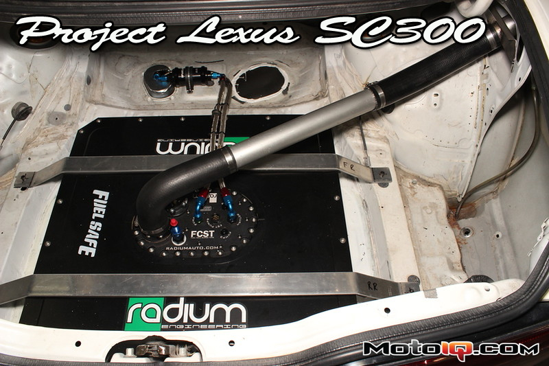
A 90-degree fuel elbow and short length of aluminum and short length of tube connect everything together.
You can see the general routing that we were aiming for. A couple of pieces of hose, some hose clamps, some short lengths of barbed tube and we are almost in business. But it would be nice if the new filler neck was more securely attached to the chassis.

The beginnings of the filler mounting assembly.
A trip to the sheet metal pile and a couple of measurements gave us the foundation for the filler mounting assembly. A couple of slices with the cutting wheel and then a few passes with a sanding “barrel” gave us a nice hole to work with.

The hole and mounting piece are test-fit.
Many little steps, remember? Back and forth until the hole was as close to mating to the tube as possible, some time with a hammer and a metal brake, and we were almost in business.

The filler mount is welded to the filler neck.
A lip provides some extra rigidity and everything is ready for welding. This isn’t a seriously structural weld, but a little care helps to ensure it looks good and will be strong. Remember, a clean weld is a happy weld.

Even in anger, this filler neck should stay in place.
Bolted to the car now, the filler neck should be pretty secure and survive insertion of a fuel hose. Since the factory precautions for overfilling (flaps and such) are no longer in place, being sure not to fill to more than the cell capacity is somewhat important. While the Radium filler neck has a rollover flap valve, it likely will not prevent overfilling and is not designed to do so.


