
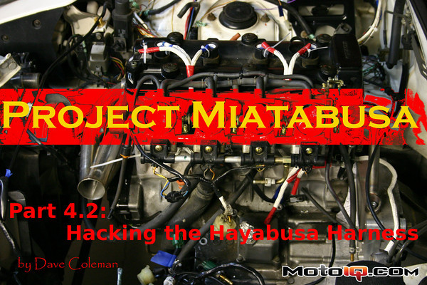

Next up in our pile of partially finished projects is making the Hayabusa's engine harness fit properly in the Miata. The Hayabusa is fuel injected (not always an obvious thing on a bike) and runs a pretty sophisticated speed-density engine management system. Each cylinder is mapped individually to account for the fact that the Hayabusa's cylinders all breathe differently. the center two cylinders have slightly longer intake runners than the outer two, and the 4-2-1 header is actually paired incorrectly, or at least unconventionally. None of this is accidental, of course. Both of these strategies reduce the power peak, but spread the powerband over a wider rpm band, all in an effort to make a 173-hp crotch rocket a little more manageable.
The service manual shows rough images of each cylinder's fuel map, which gives you a decent idea of how different each cylinders fuelling is.

None of this is relevant at this point, though. All we're trying to do at the moment is get the whole Hayabusa engine management system stuffed into the Miata and working properly. The Hayabusa harness has all kinds of bike-specific traps we're not used to, like kick-stand switches, I-fell-off-my-bike-and-I-can't-get-up switches and nonsense like that.
Rather than figure all this stuff out for ourselves, we shipped the harness off to Peter D. Motorsports, a Dwarf Car shop that deals with bike-powered cars all day long. Peter D. has a harness trimming service that makes the harness car ready for $150. That seemed like a great time saver, and in the end we still think it will be, but naturally, we overlooked some details on this first try.
The physical layout of the Miata engine bay doesn't really agree with the shape of the Hayabsa's harness. Plugging everything in leaves a messy spider's web of wires all over our work of art. That just won't do…
So, the unfinished project this time around is re-re-trimming the harness to follow a Miata-friendly layout. And the first step there is figuring out what a Miata-friendly layout looks like. Where should we mount the ECU, for example? The stock Miata ECU moved around from year to year, sometimes residing under the dash, sometimes under the passenger's floorboard, and sometimes behind the passenger's seat. The Hayabusa's ECU mounted under the seat, sitting in a little ECU-shaped plastic home and secured with a rubber strap. The Hayabusa ECU is at least a generation newer than the Miata's, meaning its smaller, lighter, and much more weatherproof. The connectors are water-tight, and as you can see in the picture below, the whole ECU is potted in a rubbery goo, making it substantially more rugged than the circuit board floating in a metal box that is the Miata ECU.

All this compactness and watertightness opens up new mounting opportunities. Similar ECUs are mounted in the engine bay on modern cars, but with the Hayabusa's original mounting in a relatively cool part of the bike, we figured it was safer to keep it away from the heat, just in case some little diode in there was heat sensitive. After jamming the ECU in every nook and cranny we could find, its natural home turned out to be in the cowl, exposed to some of the elements, but in the shade and away from the engine.

Swinging the windshield wipers through their travel reveals just how perfectly the ECU fits here. Half the box is thin, almost as if those clever Suzuki guys were thinking they better make sure it clears Miata wiper hardware…
With no mounting tabs on the plastic ECU housing, we'll be mounting it here with industrial strength Velcro.

The next mounting challenge is the rectifier. This is the magic box that takes all the AC noise coming from the alternator and turns it into 12V DC. Based on the giant cooling fins, we were also guessing this one didn't want to be anywhere hot. It found a home right next to the ECU.

As luck would have it Mazda anticipated this problem and left two perfectly spaced mounting holes in the cowl for attaching Suzuki rectifiers. The hole on the left was filled with a rubber plug, while the hole on the right was used for a plastic mounting clip to hold the clutch line. We replaced the clip with an Adell clamp, and bolted in the rectifier as Mazda and Suzuki intended. Thanks guys!

Now, about that wiring harness… Making that spaghetti look clean is actually pretty easy if you tackle the project the right way. My way is to make a wiring harness out of rope and tape, running the rope where you want the wires to go and taping the ends with labels that correspond to each connector.

As you can see, virtually every connector is on the same side of the engine, and the harness will be both tidy and tucked away under the intake manifold. Now, this is as far as we've made it on this project so far, but I already did a similar project on the Rally Beater several years ago. The photo below was taken while the old, messy wiring was still in place and the new, clean, rope harness was being laid out.

Zip tying the rope to a chunk of pegboard makes an easy template for trimming the harness. Just zip down the ECU connector at one end, un-wrap the harness, and start laying the connectors down in their new homes. This breaks down a big, confusing wiring job into easy steps on a nice, convenient table. Since all you're doing is lengthening or shortening wires, there is little opportunity for mistakes.

Once we're done making this harness, the plan is to send the ropes over to Peter D. so he can offer his harness trimming service in a Miatabusa-specific way.
All the Miatabusa you can handle:
 |
 |
 |
 |
|
 |
 |
 |
 |
 |
 |
 |
 |
 |
 |
 |
 |
 |

1 comment
Hi,
I am hoping that you can help me with a question. I am in the process of building a reverse trike with a Hayabusa engine. We split the 2007 wiring harness last night into the section near the engine in the back and the part that goes in the front and extended the wires. The engine was starting fine until we cut the wires to the left and right handlebar controls. We rewired the power switch and start switch just to check things and now there is no power to anything. All of the fuses are ok including the starter relay fuse. Do auxiliary systems, such as headlights, horn, turn signals, etc. need to be connected as well to for the dash to have power and for the engine to start?
Thanks, Mark