
,
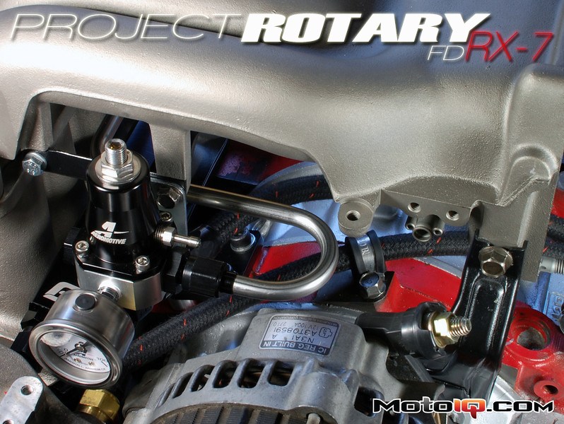
The final main component that is needed to complete the engine side of this project's fuel system is a pressure regulator. For this we turned to Aeromotive, the industry standard in aftermarket fuel components, and picked up their EFI Bypass Regulator and dry fuel pressure gauge. We chose to use a dry pressure gauge because liquid filled gauges can read different pressures at different temperatures. Using a dry gauge will eliminate this variability.

Aeromotive EFI bypass fuel pressure regulator. It is a high-flow 1:1 rate unit that increases fuel pressure linearly with manifold pressure. The pressure gauge is dry to ensure accuracy at all temperatures.
The fuel pressure regulator chosen increases or decreases fuel pressure as manifold pressure changes and does so at a 1:1 ratio. So if the base pressure is set to 43.5psi and the engine is running at a manifold pressure of 20psi, then the fuel regulator is actually increasing the fuel pressure to 63.5psi. This is important because you want the pressure differential across the injector (fuel pressure minus manifold pressure) to remain constant at all conditions. The result of this constant pressure differential is consistent fuel flow through the injector and into the intake manifold at a given injector duty cycle.

Another view of the Aeromotive fuel pressure regulator, mounting bracket, and gauge. The fuel pressure regulator features dual -6AN o-ring boss (ORB) inlets, a single -6AN ORB outlet, a 1/8″ NPT port on the front for a pressure gauge or transducer, and a pre-installed vacuum nipple.
For this build only the right fuel inlet is used and the left inlet is plugged. Installed in the bottom return port is a -6AN 90-degree swivel adapter to give adequate clearance to the coolant pressure sensor in the back of the water pump housing. The fuel pressure gauge is currently installed in the front port of the regulator, but there are future plans to install a tee before the gauge so that a pressure transducer can be used to datalog fuel pressure.

The final resting place for the Aeromotive fuel pressure regulator on the upper intake manifold via a simple custom bracket. The front of the upper intake manifold is a common mounting location due to the direct line of sight to the pressure gauge and convenient access to the regulator's adjusting screw/lock-nut. Also, like the Xcessive lower intake manifold, the upper intake manifold was ceramic coated to further block radiant heat from the engine.
With all the core components installed to the engine, plumbing the fuel rail and regulator is all that we have left to do. This build features a combination of hose and tubing with the basic premise being, use tubing wherever possible and hose everywhere else.
The hose used for the fuel system is all Aeroquip Startlite hose which is elastomer lined with Kevlar and Nomex overbraids that make it a strong, abrasion resistant and fire resistant alternative to stainless steel braided hose while still being much lighter and significantly more flexible. All hose ends are black anodized aluminum.
The tubing used is 3/8″ double-annealed seamless 304 stainless steel. The ends of the tubes are 37-degree flared for AN/JIC fittings and feature Earl's tube sleeves and nuts. Since the chassis side of the fuel system has many more tube and hose assemblies, the bulk of the plumbing details will be covered in the next article when that is discussed.

Fuel hose and tube assemblies for the new fuel rail and regulator setup. The tube assembly is used between the FFE rail and Aeromotive regulator inlet port where there is little relative movement. The hose assemblies are used between the engine and firewall where relative movement is greater and hard tubing would be a poor choice. More detail about the design and creation of hose and tube assemblies will be covered in our next article.

Everything on the engine side assembled. It is amazing how clean an engine with the bare essentials looks compared to a full OEM engine with all the emissions/turbo solenoids and vacuum lines (the Rat's nest as it is known in the RX-7 world).

Better picture of the fuel tube/hose assemblies and their routings. Using p-clips is a great way to ensure that all hoses are routed where desired and won't rub against other components.
That pretty much wraps up the engine side of the RX-7's fuel system. Be sure to check back very soon when we talk about the chassis side of the fuel system. There is still a lot more fuel components and engineering goodness to discuss.
SEE MORE PROJECT [ROTARY] FD RX-7 HERE
Sources:
Aeromotive
Full Function Engineering
Xcessive Manufacturing

1 comment
Where can I purchase these primary plugs?