
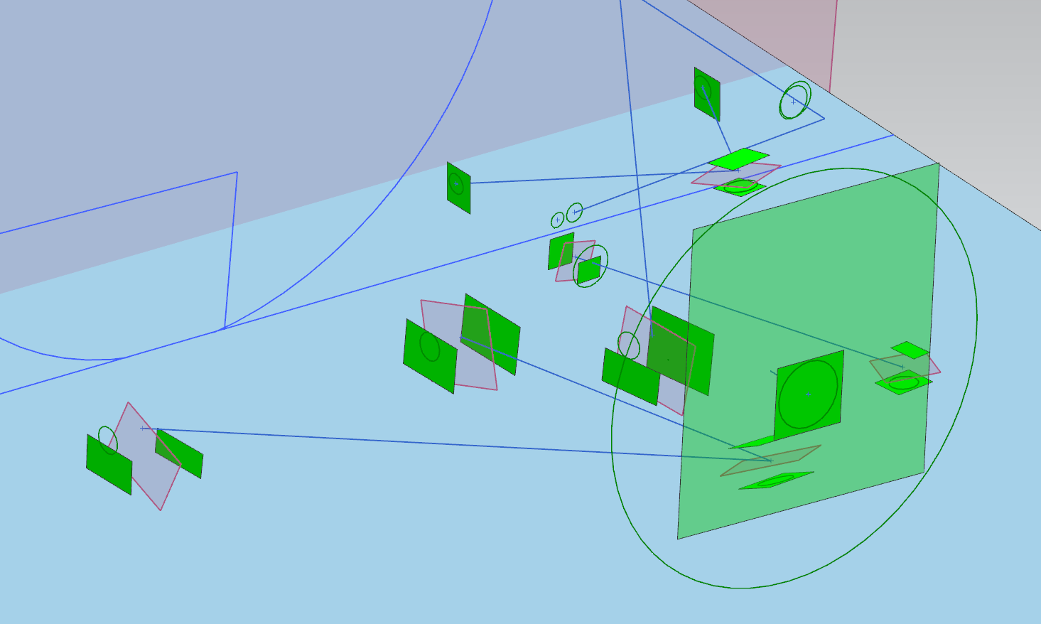

If you envision a double-a-arm suspension, you can kind of make out the components here.
With the front corner done, we could then do the back corner. This means we had to move the CMM arm to a new location. Because we had marked the half-wheelbase line and the 4-foot line, it didn’t matter where the CMM arm ended up. We were always going to establish the coordinate system in reference to those floor marks, and I’m somewhat confident that, here in Georgia, the ground wasn’t going to relocate.
If I was going to attempt this again, I would have made many different choices. Doing this with a larger CMM arm and a vehicle lift would have made the job easier and faster. The various CMM manufacturers offer some huge arms, and it would have been possible to place the CMM more or less at the vehicle center and still reach all of the suspension. Sure, you would need some kind of really tall stands so that the vehicle could sit on its weight and at ride height. But that’s relatively easy to accomplish.

After all the measurements were taken, Rob Lindsey of Morlind Engineering took the output from the measurement software and loaded it into his own CAD software and then “assembled” the car from the two sets of measurements. He then exported the 3D coordinates into a spreadsheet and gave that spreadsheet to me to plug-in to rFactor 2.

This spreadsheet is pretty intense. It has many hundreds of cells for data points. The suspension pick-up points are just one tab. There are data points for the brake system, the dampers, and even the damper bump rubbers. Fortunately, companies like StopTech, Penske, and Figs Engineering are willing to share data with me. Granted, much of it I could have obtained myself (eg: shock dynos, brake rotor weights). Sometimes, though, just asking gets you what you want.
The rFactor 2 forum has many helpful people who are willing to assist in making vehicle mods. I’ve gotten tons of assistance in their forum, in this thread specifically, for helping fill out the spreadsheet with the necessary data based on the real-world measurements. If you keep tuned in to that thread, you’ll be able to track the progress. I’ve been swamped lately and haven’t been able to slog through some of the data, but I’m getting close.
Hopefully, by the end of the year, I’ll be able to drive my simulated SC300 and tell you how well it performs against reality. I’ll also release my MotoIQ Project SC300 mod for rFactor 2 for everyone to download and use. All of this, of course, is largely made possible by the awesome services provided by ECM.
And maybe because I paid a guy in Ukraine to help get the 3D model part done, mostly so that I don’t have to drive a sneaker around virtual Road Atlanta.
Although that might be just as fun.
11 comments
There’s places that will do tire testing and it’s… expensive but if you keep the test matrix down, in the 4-figures level. Would be interesting to add that to the mix. I’m figuring that most of the time in sims it’s not that the tire model itself has issues, just that it’s filled with variables that people are guessing at.
The most important thing is that the driver understands how the tire develops grip, and how to keep it at the proper temp. You can collect as much data as you want, but if the driver doesn’t understand that data, it is worthless. The pneumatic tire has been around for over a hundred years and there’s only one book written about it? Sad.
This is a must read for anybody serious about racing:
https://www.sae.org/publications/books/content/r-351/
Very interesting, great work Erik! I had no idea this type of equipment could be rented and used by near mortals.
The wheels are turning on other ways this type of equipment could be used.
@Dan: Where / who does the tire testing? I do have a spare that I could trash…
@Erik L: Oh yeah? What are you thinking of measuring/scanning?
Calspan does – if you are willing to be flexible on schedule and don’t get too complicated it helps hold the cost down, and the gent I was talking to was willing to deal with it as a smaller project.
Dan – if you find me on Facebook or email me at erikmjacobs (gmail) would you tell me who you spoke with? I’d be curious to talk to that person.
Mailed. Though as I mention in the email I just used the contact form at https://www.calspan.com/contact/ and they got back to me in a couple days.
Great article of the process. Well done.
Thanks Brad!
Yeah, I really like this article. I wrote my own code in MATLAB in college using Dixon’s equations and precise measurements (by hand) of the EG6 Civic suspension. I had so many parts lying around, it was pretty much a no brainer. You can learn how to avoid so many mistakes through simulation. While I did some minor modifications using a LCON traction bar which allowed me to remove the rear half of the LCA, and drop 8lbs of unsprung weight, I also gained enormous appreciation for Honda suspension engineers. The stock bump steer curve could not actually be improved upon without new spindles. Simulation proved to me that some things are better left alone.
This is a great book, BTW. It is the ‘Bible’ for suspension engineers.
https://www.wiley.com/en-us/Suspension+Geometry+and+Computation-p-9780470510216
Thanks, Joe! That looks like a real textbook there. Probably well over my head. As you’ve learned some things are best left alone, I have learned that for some things I should probably outsource. Suspension engineering is one of those things. I’m fortunate to have folks like Figs Engineering, Mike Kojima, and Rob Lindsey (Morlind Engineering) available to me!