
In the last installment we disassembled our SR20 in preparation for machining. Now comes the fun part where we get to pick all the parts for the new build! We’re going to start with Engine Management.

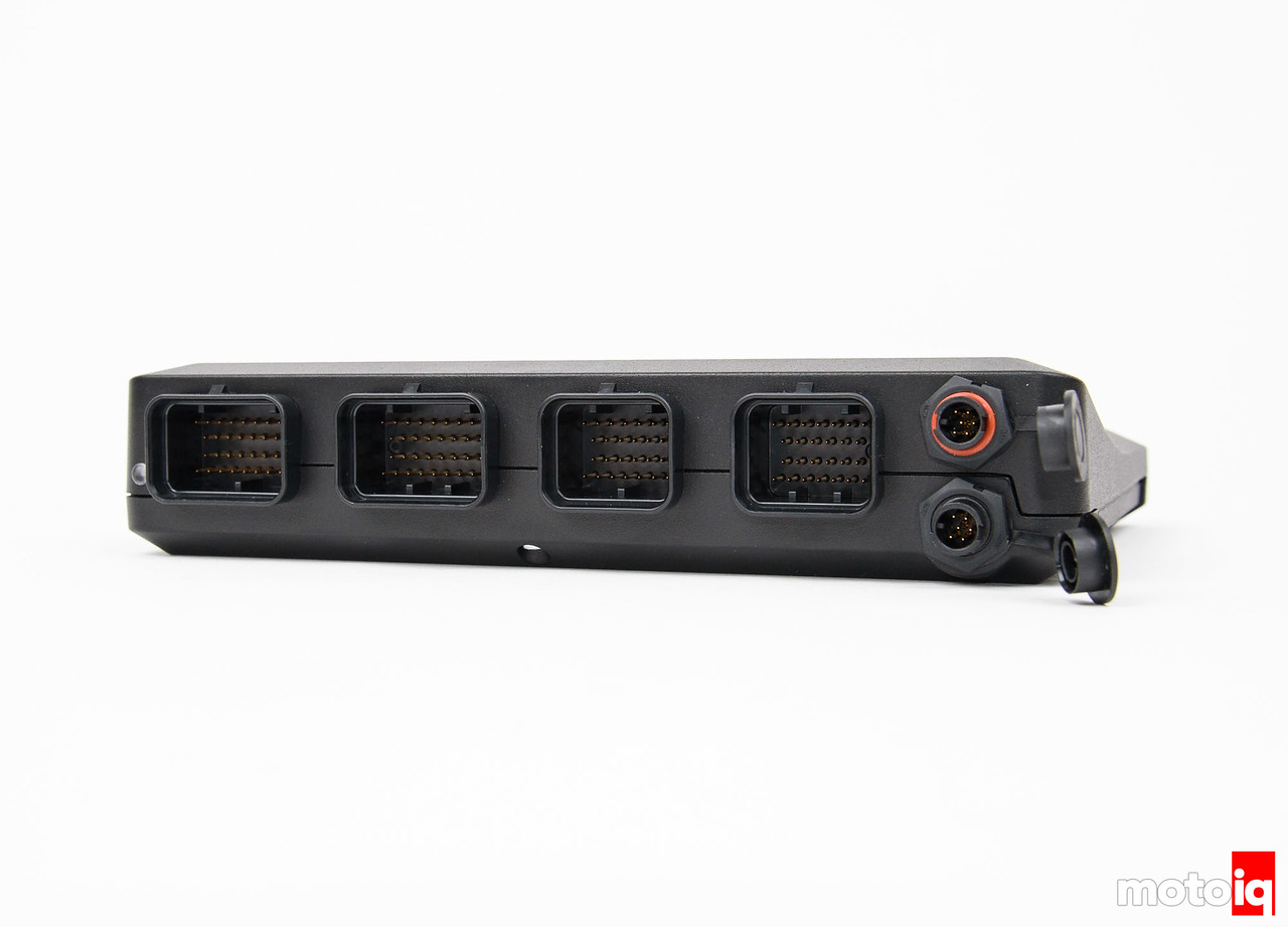
We selected the Thunder due to its overwhelming amount of inputs and outputs which provides us a universal, future proof Engine Management solution. This ECU can basically run any motor you throw at it. Some of the Thunders main features are an onboard 3 axis accelerometer, two EGT thermocouple inputs, two onboard Lambda controllers, and two e-throttle controllers. Here is a complete breakdown of the I/O capabilities of this ECU.
Inputs:
- 16 x Digital inputs
- 4 x Temperature inputs
- 16 x Analog inputs
- 2 x Trigger inputs
- 2 x Knock inputs
- 2 x LSU 4.9 Wideband lambda sensor inputs
- 2 x K Type Thermocouple inputs
Outputs:
- 8 x Peak and Hold injection drives
- 8 x Ignition drivers
- 18 x Auxiliary outputs*
- +5V Sensor power supply
- +8V Sensor power supply
Communications:
- 2 x CAN bus
- 1x Serial (RS232) connection
- 1x USB tuning connection

The way Link pins its ECU’s is actually really clever. It’s pinned in such a way that each of the 32 pin A and B connectors drive 4 cylinders, or one bank of a V8. The 26 pin C and D connectors are used for additional I/O. Most of Link’s wire-in ECU’s also share the same pinout for the A and B connectors. So let’s say you have a Link G4+ Xtreme ECU running your engine, and you decide to upgrade to the G4+ Thunder for the extra I/O. You can literally unplug your Xtreme and just plug the Thunder into the same harness and it will work.

11 comments
Conformal coating isn’t really used for weather proofing. It can be, but if the ECU case is unsealed you really don’t want to rely on conformal coat to protect your board. It’s more for protecting against solder balls on fine pitch components. I also find it interesting that they pot the big capacitors. I suppose that’s for vibration resistance, though that’s not something we typically do in the OEM world. I also find it interesting that there’s no heat sinking on the baseplate. The board looks to be bonded into the baseplate (usually with some type of thermal grease or paste to get conductive heat transfer), but the baseplate itself has no heat sinking fins. I’m curious, what are the mounting requirements from Link for this ECU? Is it cabin only?
Potting the caps HAS to be done. Without it the caps have zero chance of staying on over the years. Even the cheapest Chinese boards have some sort of silicone (or at least hot glue) on caps to prevent them from breaking off.
Also, a properly conformal coated board can be completely submerged in water temporarily and still work. You can find countless demonstrations of this on youtube.
FYI ECU package design is my day job, so my experience in this area is a bit more advanced than YouTube videos. A conformal coated board can last submerged for a short time…but if that’s your only sealing method it’s not good long term. Also, conformal coat can’t be used on leadless components (like BGAs or QFNs) because it causes solder cracks. This is why I asked about Link’s mounting requirements. If it’s interior mount, the point of the conformal coat is to protect against dendrite growth between leads. This is common in fine pitch components, especially those exposed to varying levels of humidity.
You can absolutely get those type of cap to last without potting or RTV. We use similar caps on our GM ECUs and those are designed for a 10 year lifespan in the engine bay (fairly high vibration, high thermal shock, and lots of temperature cycling plus submersion). For our SMT caps there is no added adhesive, though we do have a couple of through caps that are potted because of their size (they’re more than twice the size of the caps shown here). There’s a lot you can do to protect at risk solder joints before resorting to potting. Again, this is why I asked about Link’s mounting requirements. An interior mount would lead me to believe they designed for relatively low heat, no splash or submersion, but high vibration. Typically Motorsport applications have very high vibration throughout the cabin, hence the need for potting on the large caps.
I’m not saying Link’s design is bad or wrong, I’m just comparing their design priorities and methods to ours.
Yep, Solid Mounting a engine to the tub would do that. It rattles and jars your teeth lose on a racecar. Thats why all the POT is used in those aplications. I personally would use POT as much as I can, just to rather be safe then sorry. But then again: Thats just me, and I don’t have sound reasoning for that other then vibration. Nor do I know the drawbacks of using POT, except from a higher heat buildup since its trapped?
The latest itteration of the Formula 1 ECU is built by McLaren Applied Technologies which is manditory for every manufacturer since 2007 or 2008 I believe? It has been altered since though, Because of KERS / DRS / V8 NA engine to V6 turbo Engine and off course fuel limitations.
And I just found out the same applies to the NASCAR ECU and INDYCAR ECU: McLaren Applied Technologies
For very high vibration specs (like motorsport ECUs) then yes, securing the components in potting is definitely advantageous. I know on our AFMs we pot the PCB since it is engine mounted and sees a huge vibration and temperature delta.
Like I said before, I’m not saying Link (or McLaren for that matter) are designing poorly, I just found it fascinating to compare their design to the stuff I’ve worked on. Their goals are different to the ones my OEM customers have, so their design path is going to be different from mine.
Or just slap a nistune board on the stock ECU and save 1700$.
The G4+ thunder surely packs a lot of features, but it costs ~2200$ with a harness.
A nistune type 3 board with the consult cable and the licence costs ~430$, tax included.
For that money the stock ECU becomes a real time tunable ECU for a fraction of the cost, with launch control, fan control, VCT control and total flexfuel capabilities.
All >350WHP sr20det we have here run on the stock ECU modded with a nistune board. It just does the job, and the price difference can go into “go faster reliably” parts. IMHO a G4+ thunder is totally overkill for that kind of engine.
All these people running cheap Nistune boards are half the reason why SR’s have a bad a rep.
You really can’t even compare the capabilities of a full standalone ECU to a daughterboard. They exist in different dimensions. Sure, your SR will run on a Nistune board, but a Nistune board can’t tell you if your SR is about to blow up. At the end of the day the best ECU is the one that saves your engine.
If you’re on a tight budget, you can get a Link G4+ Atom 2 for $650 that will run an SR. The reason we went with the Thunder (apart from it’s insane capabilities), is that we also want to use this ECU to run our future (shhhh) RB25.6 build. Getting a wire-in ECU with enough outputs saves us having to get two ECU’s.
For motorsport applications you see the pot way more often. When I was in F1 it was used on most circuitry. Soldering shook apart with those kind of vibrations. POT prevents it.
As for the heat sink: Probably down to used voltage? When you only trigger relais a low voltage should suffice. It only says output voltage, not working voltage?
For really extreme applications such as F1 I can definitely agree that potting is the way to go. That being said, for much “calmer” applications such as this I’d pick conformal coating any day.
Yep! Cleaning would a hassle if you wanted to repair anything. But since everything is sealed anyway, that’ll never happen. So if its broke, just plug in another one.
That being said though: I can imagine potting would also work for the offroad guys? It isn’t the prettiest site, but if it works it works….
I was hoping for a continuation but its been years since the second part came out so I’m guessing no more articles will be published. Either way it was a great read and it definitely helped me get started on the tear down.