The coolant pump and electronics live at one of end of the aluminum battery pack housing. It looks to be in a separate compartment from the battery cells and therefore not immersed in coolant. The aluminum housing itself looks to be sand cast with ribs on the outside for strength and heat transfer surface area (fins). The strength is important in a crash situation to prevent any damage to the cells which could cause them to go into thermal runaway; i.e. catch fire. Once a lithium-ion battery cell catches fire, it will basically burn until nothing is left. You cannot starve it of oxygen because the lithium acts as the oxidizer feeding the burn.


A benefit of the liquid immersion battery cell cooling concept is the coolant can quickly absorb heat from any hot spots in a battery cell and potentially prevent the cell from going into thermal runaway. If a cell does go into thermal runaway, the coolant can absorb the heat and hopefully prevent the neighboring cells from catching fire. The coolant pump looks to suck the hot battery coolant from the bottom of the battery cell compartment of the battery pack. Then it pumps the coolant over to the oil-coolant heat exchanger mounted to the side of the battery module on the outside. After the battery coolant reduces in temperature, it flows through a distribution manifold running along the top of the battery cells to spread the coolant mostly evenly across the battery pack. The coolant works its way down picking up heat and the cycle repeats. The battery cooling fluid can be quite thick when cold, so I figure that is way the pump sucks in fluid that has already picked up heat from the battery cells and become less viscous.

Doing some quick math, there are 7 cells stacked head to tail going down the length of the pack. And then there are 8 rows of cells. So that makes 56 cells in series. With a nominal voltage of 3.65 V per a cell, that’s 204.4 V. Inside the overall aluminum battery pack are actually two sub-modules with each sub-module having 5 sets of the 56-cell series stack in parallel. So, you put your two 204.4 V battery sub-modules in series and that gets you the overall 400 V rating of the battery pack. The pack is rated at a capacity of 6.1 kWh. That means each cell has a capacity of 6 Ah for a 21700-size cell assuming the 3.65 V nominal cell voltage. That capacity is pretty far up there, maybe the best out there right now for a 21700 cell.

One of the challenges in making a battery module using cylindrical cells is making the electrical connections because there are thousands of them. Tesla spent a very long time developing their wire bonding technology. Other battery modules have used some form of welding. None of the techniques are easy and they relatively often fail. Well, the cells used here in the Mercedes AMG pack use four little prongs which grab the next cell and it is just a simple mechanical joint. Not much different than putting AA batteries in every electronic device for the last half century.

Here you can see how the prongs create the electrical joint to the next cell and the final end plate. It is just like stacking Legos. Very clever.

Holding the stack of cells together look to be threaded rods running the length of the cells and a nut on the end. To prevent leaks of the battery coolant fluid, there is a little gasket between the upper and lower aluminum portions of the battery pack.
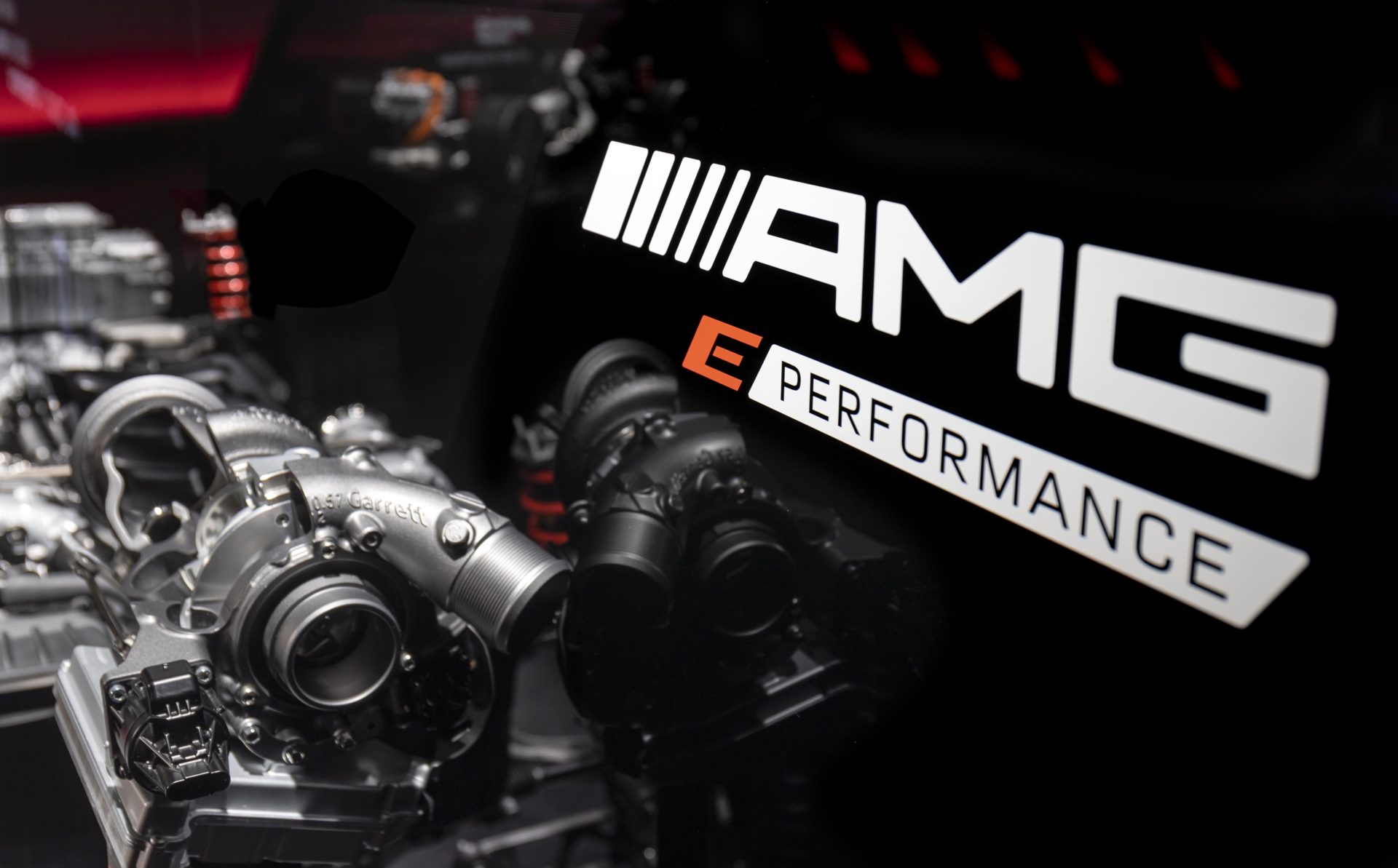
Technology continues to march on and this is another case of having your cake and eating it too. A decade ago, people were complaining about downsized turbo engines which were intended to improve fuel economy. We wrote about downsized turbo engines nine years ago. Yeah, you lose some sound compared to a larger displacement naturally aspirated engine, but downsized turbo engines are great if you like easy big power and you get the better mpg to boot! With hybridization, you get more power, anti-lag, and better mpg too. Formula 1 has been optimizing the hybrid and e-turbo engine combo since 2014 and efficiency has increased from 29% to over 50%. The F1 cars today are making more power than the old non-turbo V8s while getting drastically better mpg too. Now you can have that technology in your driveway from Mercedes AMG.


23 comments
Great article!! I take it this battery pack is solely for the turbo? why not tap into an existing hybrid drivetrain to power an “e-turbo” or is the goal specifically about power/capacity/emissions. also, seeing the batteries like that seems obvious now, lol.
The E-turbo is part of an already hybrid drivetrain. The E-turbo needs very little energy, only a couple seconds to spin up the turbo and get the engine into boost and making enough exhaust flow to spin the turbo without electric assist. It would cost too much to only have high voltage electronics and battery for just an E-turbo. But an E-turbo is a small cost add-on to an already electrified hybrid drivetrain that already has a turbo engine. As the European makes have already made a bunch of hybrid cars with turbo gas engines, it was only a matter of time for e-turbo to get implemented. You’re basically paying for an extra inverter and the small motor in the e-turbo, and a few more HV cables and signal wires.
As for the size of the electric motor powering the wheels, I haven’t seen AMG say power it is. But considering they say the battery can put out 150kW of power, we can make a good guess. Conservatively, 90% of that 150kW turns into electric motor power which equals 135kW. And that equals 181hp. We add 181hp to the 442hp of the gas engine and we have an estimated total output max of 623hp. But typically, the combined output is lower than the individual max outputs combined; the electric motor typically isn’t asked for max power at the higher engine speeds. But… that’s in your everyday boring Prius type hybrid. So… hard to saw what AMG has done.
As a thermal – fluids person I enjoyed this article. Thanks for sharing.
Yup! Even with the transition to electrification, everything still needs cooling. There is a lot of room for optimization and creativity in the thermal fluid systems.
Thanks for explanation!! I assumed that would be layout.
This makes me wonder where they place this battery in the given vehicles: as 21700 cells (7 rows) alone stack up to 490mm long, and then roughly 252 wide and 168 high as arranged (19.3″x9.9″x6.6″). Do they stuff them where a spare would go, or cut into fuel capacity?
My dims don’t account for the casing itself nor the pump and control board side of things.
Definitely a cool breakdown on the system however. Those 6ah batteries, I want em!!
Front what I’ve seen, the plugin hybrids typically put the battery pack in the floor of the rear cargo area. Old school spare tire location. I just looked up a picture and they have it sitting above the rear electric motor. So over the rear axle centerline. Basically behind the rear seat then? On the 6Ah cell… Yeah, I had to double check my math. Caught me by surprise on the capacity too. Granted, I’m not up to speed on the latest battery cell specs, but it’s more than anything I was aware off. Still the possibility my math is wrong! It does depend on assumptions used for cell voltage and I assumed nominal 3.65V
Such a great article! Thanks Khiem
Appreciate it!
Nice write up Khiem. Regarding the mechanism on the compressor side, Garrett (under Honeywell at the time) published a number of patents on upstream mechanisms aimed at extending the usable compressor map. The common theme one will find if they read these public documents is that something is introduced into the flow stream upstream of the compressor effectively reducing the inlet flow area, and removed from disrupting flow once the operating condition seems it beneficial. Such a system would benefit any turbocharger where both low end torque and high end power are constrained by the compressor map width. My suspicion is that this is what is in this e-turbo and not a compressor bypass. Yours is the first time I’ve seen it mentioned in an article and Garrett has been quiet about the technology which leads me to believe they are waiting for a suitable industry conference to unveil it.
Thanks for the insight! Well, it can’t be too much of a secret or you’d think they would have hidden it better. One of these days, maybe I’ll do a patent search to try to find it.
You know…. way back in the day, I had the idea of a recirculation path to effectively increase map width. Say the compressor wheel would surge at less than 15 lbs/min but the engine was only asking for 12 lbs/min, So the wheel could flow 15 lbs/min with 3 lbs/min getting recirculated so that only engine only see 12 lbs/min. Looking at this a bit more, it looks kinda like it just moves a part of the shroud contour away from the wheel which I guess would effectively reduce the mass flow of the wheel. I guess the information will come out soon enough.
“ There’s also a new and larger turbocharger residing between the engine and the front bulkhead. This unusual location necessitates better cooling techniques to prevent the blower from overheating under sustained high-rpm operation. This is achievable thanks to the new coolant plumbing, but most of it has something to do with the new engine cover that directs cooling air to the turbocharger. Mercedes says the 415-horsepower ‘S’ version of the M139 also utilizes cooling air from the HVAC system when needed.”
That’s pretty interesting. I think that the HVAC cooling is what you saw on the compressor side of the housing.
The press release also quotes roller bearings.
“ Equally, the increased sophistication of the post 2014 power units brought complication to the cooling system with thermal management of the Hydrid system’s; Battery, MGU’s and Control Electronics. These run at much lower temperatures than the ICE, their cooling is achieved by either water-based coolant or dielectric fluid (oil). Running at around +50c they greatly affected by the ambient temperature going above 30c.”
That was my first thought reading this article. We know that oil has something like half the specific heat capacity of water, so it seems like there would be ambient temperature situations where you could overload the battery cooling system on the Merc.
The battery is also located above the rear axle, so I don’t know how it gets any airflow over the case.
Got a link to the press release? The language is weird… nothing unusual about the location of the turbo at all. The engine is longitudinal layout and the turbo is hanging off the side, like a bazillion other engines. Marketing though… I get it, they have to make it sound special. In general, turbos don’t need external airflow for cooling them, but you want airflow around the turbo to keep everything around it from baking. Evo X and Nissan GTR have NACA ducts in their hoods for this reason. The WRX diverts some of the air going into the hood scoop over to the turbo area. With this e-turbo, keeping the power electronics cooler is a good thing.
In the picture from Mercedes, the bearing is most certainly not a roller/ball bearing, just a good ole journal bearing. So either the cutaway turbo is not representative of the production unit, or the press release is wrong. I’d go with the press release being wrong as the media teams often do not speak to the engineering teams. Also, doing a bearing change from journal to ball bearing would mean redoing all the validation testing, so months and months of work.
On the battery cooling, battery cells typically like to be around 35C-40C. Give or take. It seems Mercedes likes to keep this pack around 45C. The little bit warmer I think reduces internal cell resistance at potentially a trade-off of life, but 45C is not by any means outrageous. It could be that newer cells are more tolerant of heat too. While the specific heat capacity of the dielectric oils are lower than water, you can just have a higher flow rate to compensate. All high performance EVs have a chiller to sub-cool the coolant below ambient. So the cars run the A/C system and some/all of that cooling capacity goes to cooling the battery cooling fluid below ambient.
I have personally never heard of ‘HVAC cooling’ of a turbo, either. But, it has been quoted in a couple articles, so I am sure they are doing something unique. It’s really hard to figure out the plumbing with the pics available.
I totally agree with your analysis given the pictures presented, but now, I honestly think that there might be two different turbos for the M139. One for the S model, another for the lower power model:
From Motortrend:
“The twin-scroll turbocharger now employs roller bearings to reduce friction and an electronic wastegate actuator for more precise control. “
“On S engines, the air-conditioning system helps to reduce the intercooler’s temperature under maximum-power conditions.”
https://www.motortrend.com/news/amg-m139-turbo-four-cylinder-engine-specs/
This article shows what looks like a different turbo than the S model, but it has the same M139 model number:
https://www.carmag.co.za/news/rumours/mercedes-amgs-new-e-turbo-used-m139-four-pot-report/
The M139 with 415 hp is from the A45 AMG and does not have an e-turbo. I am 100% sure the e-turbo is journal bearing, and does not have HVAC cooling.
It doesn’t look like my last reply made it up (maybe the links got blocked automatically.)
But, there must be two different turbos. One must be exclusive to the S model. You can see it in the pics on Motortrend. One has the ‘mystery actuator’ and the other doesn’t. I would still like to know what exactly it does because I have no idea how ‘HVAC cooling’ of a turbo would work.
“Furthermore, the shafts of the compressor and turbine have roller bearings for the first time ‑ as in the top output variant of the AMG 4.0-litre V8 engine in the AMG GT 4-door Coupé. The roller bearings reduce mechanical friction within the turbocharger to a minimum. The charger therefore responds more readily and reaches its maximum speed of up to 169,000 rpm more rapidly.”
“ Fresh air is used in addition to oil and water to cool the turbocharger. This is directed specifically to the charger from the radiator grille, via the engine cover designed as an air deflector and ducts beneath the bonnet.”
“ The turbocharger resides between the engine and the front bulkhead. This unusual location necessitates better cooling techniques to prevent the blower from overheating under sustained high-rpm operation. Mercedes says the 415-horsepower ‘S’ version of the M139 also utilizes cooling air from the HVAC system when needed.”
Sorry, that it’s not letting me post links, but those are direct quotes from the press releases from AMG. I didn’t write them.
Ah… the Motortrend article is for the previous generation I wrote about too.
https://motoiq.com/nerds-eye-view-mercedes-amg-m139-engine/
As for the HVAC cooling of the intercooler, that’s neat and I didn’t know they were doing it. That M139 uses an air to water IC. If I were doing it, I’d have a chiller that uses the refrigerant from the HVAC system to sub-cool the water going the the IC. Just like how the high power EV battery packs do.
The photo in the carmag link without the mystery actuator, I saw that picture a year ago too. So I’m assuming an earlier development variant.
I wonder if the HVAC cooling is solely responsible for the 34hp increase on the S-model.
Your idea for the HVAC cooling sounds a lot better. I was thinking that they were just blowing de-humidified cool air over the IC, which would seem totally pointless in a hot, cramped engine bay.
I missed that first article, thanks for the link. Love these articles, BTW.
Any guess at who their battery supplier is? A123 or Saft? Haha!
So how does it compare with hybrid turbos from TTE or MACHGRADE? The hybrids deliver more power than this electric unit, is there any more downside than increased turbo lag? I mean, the lag has some old-school vibe and if the car is faster, then … it’s faster : )
There’s nothing special about hybrid turbos; they just have bigger wheels stuffed in the original castings. E-turbos took quite a while to develop and bring to market due to advances required in high speed motors, the high voltage electronics surviving the heat and vibrations of the turbo, and the necessary controls. Of course, they’ve been in Formula 1 since the introduction of the current turbo V6 hybrid era. E-turbos are being developed in many sizes.
This one is interesting https://muchboost.com/product/m139-hybrid-turbo-upgrade-mercedes-a45amg-w177/.
https://www.facebook.com/Muchboost/posta/pfbid02iPngM1DJdBUGr4whT5YUFUZcDJ7minrMdQo7pe5jPr6hLTQDfkpHRL3gA3JSjW2Kl
Is there anyone who tried TTE 560?