

McMaster Carr calls this part (5720K35) a “clamping handle with stud.” I decided that I wanted to get the splitter on and off quickly for trailering, or for whatever other reason. If one of these clamps is good enough to hold a mountain bicycle front wheel on when it’s being slammed around in shock-loaded compressive shear, it’s probably good enough to use two M8 studs on each side of the splitter to hold it on when it’s all generally static pulling shear.

I use simple M8 wingnuts (McMaster 94300A340) on the backside. You get the wingnuts mostly tight, then rotate the handle and clamp it. It’s crazy tight. It survived an entire weekend driving the National Corvette Museum track without ever retightening. At the end of the weekend, it was still super hard to un-clamp them, just like it was super hard to clamp them.

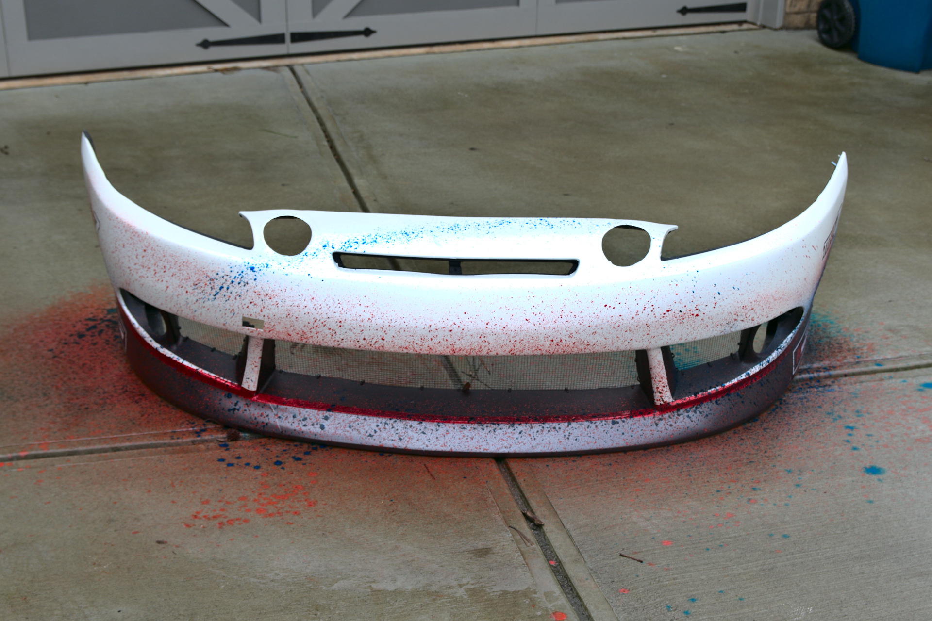
You can see the masking tape where the ramps should go in the future. Before you cut giant holes in the splitter, make sure that the ramps don’t interfere with the bumper and vice versa.
There is a problem here, though. Look at how much splitter is in front of the intercooler. And you can see that the mounts are even behind where the intercooler is. There is nothing holding the front of the splitter up against the generated downforce. The splitter is made of somewhat flexible wood. If the splitter generates a ton of downforce, it may end up bending quite a lot. If the car gets super low in the future, it could even contact the ground. The bending also means the full downforce isn’t being transmitted into the chassis. None of it is ideal. How can we fix it?
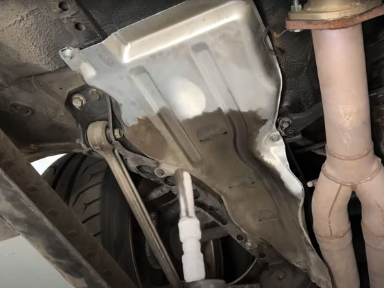
The NASA ST rules state that a front and rear crash bar must be present and must “meet or exceed” the factory unit’s strength. How about a drift-style nerf bar that some rods (stays) hang off of to hold up the front of the splitter?

The nerf bar is roughly the same size and shape as the factory crash bar, but you could probably push a dump truck with it. It’s made of tubular steel. Since the KBD bumper was designed to fit on a stock car, it meant that the OEM crash bar would fit. So an OEM-sized aftermarket nerf bar would also fit. And it does. Fit, that is.
4 comments
Have you stood on the splitter to check for flexing, yet? That’s the ultimate test. You can’t imagine how much load these generate at high speed. Just imagine the force against a 1 sq/meter plank of wood during a hurricane 150mph!
Wind Load Calculator
Dynamic pressure (N/m2, Pa): 2940
Wind Load (N): 2940=660lbs
Also, I would argue that a flatbottom is the ideal aero solution for any car. Of course, it’s just a starting point because you want to attach strakes and flow diverters around the wheels to redirect turbulence.
“Have you stood on the splitter to check for flexing, yet? ”
No, and I probably wouldn’t. That’s not a realistic approximation of the load that the splitter experiences. It’s a point load. It’s a good test in the sense that if it doesn’t flex while experiencing an extremely unrealistic loading, it’s probably strong enough. But it’s not a realistic test.
“Just imagine the force against a 1 sq/meter plank of wood during a hurricane 150mph!”
Your load calculation is also quite off the mark, I think. A splitter does not receive load against its flat surface. It’s an airfoil, not a wall. That load calculation is for wind pressure hitting a flat surface straight on. It is not the load calculation of an airfoil’s lift force at 150MPH. If I had a full 3D scan of the car (Rob Lindsey, are you listening?) we could calculate the lift of the splitter to determine the amount of downforce it provides. For a simple, flat splitter with minimal rake and no additional aerodynamic aids (the current configuration) I do not believe I am going to be generating hundreds of pounds of force. Maybe 100-150. It’s a good question for Rob.
“I would argue that a flatbottom is the ideal aero solution for any car. Of course, it’s just a starting point”
This is a contradictory statement. If it’s the starting point, it’s not ideal. Ideal and best are nearly synonymous. It means there is no room for improvement.
Is a flat bottom better than nothing / OEM bottom? Possibly. It would require testing.
Is a flat bottom the best (ideal)? No. Additional aerodynamic devices will be better than a flat bottom.
On the C5 Corvette CFD, with a similar size splitter, we saw a topside area/pressure of ~200in^2/2000pascals and an underside of ~350in^2/2500pascals. This ends up at roughly 200lbs at 150 mph but that load is distributed across a ~50″+ width.
*Note that the addition of a splitter may well add more than that amount of downforce due to changing the overall flow structure. It impacts the amount of air going under the car and around the sides which can prevent lift in other areas of the car.
Having said that, stiffness does matter (to prevent oscillations, damage, porpoising) so being able to stand on your splitter is useful, but it’s far from required.
You can see similar results in the work on the 350Z we did for Grassroots: https://grassrootsmotorsports.com/articles/against-wind-part-2/
Well, of course, it’s not going to see 660lbs, that’s a worse case scenario if it was perpendicular to the flow stream, but I wouldn’t doubt that it would see a substantial amount of that load. I would probably guess somewhere around 300lbs at 150mph, because it’s at the stagnation point and the dynamic pressure is very high on the bumper. The air has nowhere to go, and is forced to change direction and that’s what makes a splitter so effective. Also, consider that the center of pressure is located about the midpoint of the splitter, so there’s a moment arm and a substantial amount of torque is being generated on the mounting point. Any amount of flex is going to open up gaps and make the splitter less effective when you need it.
If you have some way of rigging up a whiffle tree, which allows the load to be distributed evenly over the splitter like they do with an airplane wing at Boeing, then I would absolutely love to see that data. But, I am assuming that you don’t have the time, money, or inclination to perform such a test, so the cheap and easy way is to stand on it and see if you can feel the flex with your toes.
Regarding a flat bottom, yes, I admit that it’s a starting point, but it’s certainly a good one. In fact, considering how simple the geometry is, I can’t honestly see how anyone would argue against it. Sure, some trick double diffuser with meter long tunnels will be better, but that’s certainly not easy to make or install on a production car.
The theory behind flat floors is really simple, a smooth surface is going to allow a fluid to flow faster than an extremely rough one. The higher velocity flow equates to lower pressure on the surface, and a lower pressure under the car equates to more downforce. This is all extremely well understood basic fluid mechanics.
If you want a more detailed explanation, here’s a nice video with some CFD and actual data on a production car geometry:
https://m.youtube.com/watch?v=pXYJpXKMp_E