

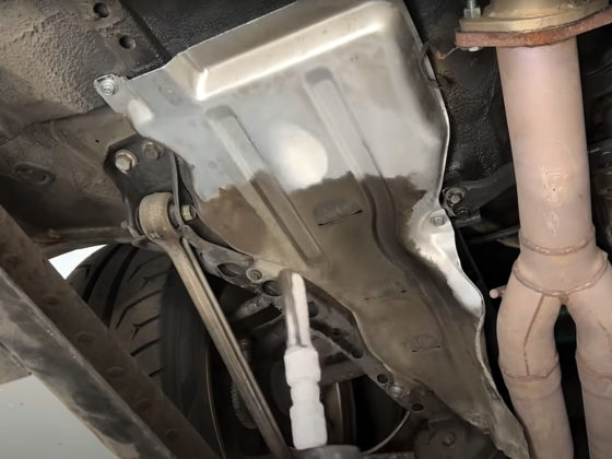
Then, a threaded tube will attach to the rod end, another rod end at the bottom, and another bracket on the splitter.

The rod ends are reverse-handed-thread from one another. One is right-handed and the other left. The tube is threaded appropriately. Because of this reverse-handedness, turning the tube either tightens or loosens it at both ends. This allows you to set the correct overall length by simply turning the stays.
A jet nut or k-nut is used on the bolts that go through the rod ends and the brackets. Jet nuts are slightly misshapen, which provides a natural locking force, and no locking washers or other hardware is required. Note, though, that jet nuts should not be used more than once, generally speaking. You can look up the MS21042 spec if you are curious. Unfortunately, there is no metric mil-spec jet nut, for your information. Pegasus Auto Racing sells metric nuts made to the MS21042 specification, though.
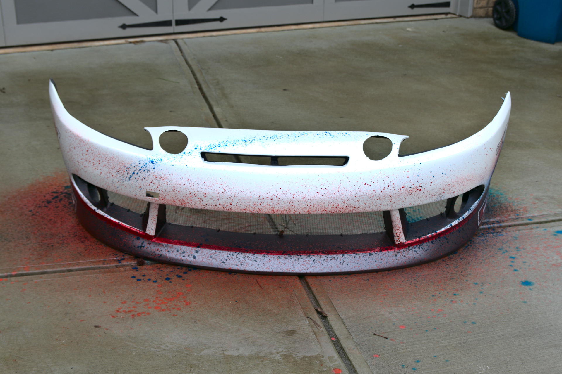
We also had to drill holes in the bumper to allow the stays to pass through from the nerf bar to the lower bracket. Figuring out the specific bracket locations, the length of the stay, and the angles was definitely a challenge of trial and error. But that’s what good fabricators get paid to do.

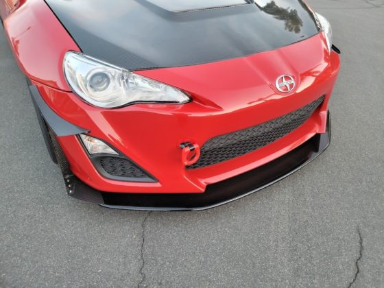
This thing looks like a real race car now! Unfortunately, I had a pretty lame weekend at National Corvette Museum for the #GRIDLIFE Time Attack. I popped off a bunch of boost hoses, got no good track time, and couldn’t go very fast. I can’t tell you if the splitter is doing anything yet. And the ramps aren’t on yet, either.
But don’t worry. I’ll be out there again soon enough. These minor setbacks won’t cause the band to split up quite yet.
Get it?
4 comments
Have you stood on the splitter to check for flexing, yet? That’s the ultimate test. You can’t imagine how much load these generate at high speed. Just imagine the force against a 1 sq/meter plank of wood during a hurricane 150mph!
Wind Load Calculator
Dynamic pressure (N/m2, Pa): 2940
Wind Load (N): 2940=660lbs
Also, I would argue that a flatbottom is the ideal aero solution for any car. Of course, it’s just a starting point because you want to attach strakes and flow diverters around the wheels to redirect turbulence.
“Have you stood on the splitter to check for flexing, yet? ”
No, and I probably wouldn’t. That’s not a realistic approximation of the load that the splitter experiences. It’s a point load. It’s a good test in the sense that if it doesn’t flex while experiencing an extremely unrealistic loading, it’s probably strong enough. But it’s not a realistic test.
“Just imagine the force against a 1 sq/meter plank of wood during a hurricane 150mph!”
Your load calculation is also quite off the mark, I think. A splitter does not receive load against its flat surface. It’s an airfoil, not a wall. That load calculation is for wind pressure hitting a flat surface straight on. It is not the load calculation of an airfoil’s lift force at 150MPH. If I had a full 3D scan of the car (Rob Lindsey, are you listening?) we could calculate the lift of the splitter to determine the amount of downforce it provides. For a simple, flat splitter with minimal rake and no additional aerodynamic aids (the current configuration) I do not believe I am going to be generating hundreds of pounds of force. Maybe 100-150. It’s a good question for Rob.
“I would argue that a flatbottom is the ideal aero solution for any car. Of course, it’s just a starting point”
This is a contradictory statement. If it’s the starting point, it’s not ideal. Ideal and best are nearly synonymous. It means there is no room for improvement.
Is a flat bottom better than nothing / OEM bottom? Possibly. It would require testing.
Is a flat bottom the best (ideal)? No. Additional aerodynamic devices will be better than a flat bottom.
On the C5 Corvette CFD, with a similar size splitter, we saw a topside area/pressure of ~200in^2/2000pascals and an underside of ~350in^2/2500pascals. This ends up at roughly 200lbs at 150 mph but that load is distributed across a ~50″+ width.
*Note that the addition of a splitter may well add more than that amount of downforce due to changing the overall flow structure. It impacts the amount of air going under the car and around the sides which can prevent lift in other areas of the car.
Having said that, stiffness does matter (to prevent oscillations, damage, porpoising) so being able to stand on your splitter is useful, but it’s far from required.
You can see similar results in the work on the 350Z we did for Grassroots: https://grassrootsmotorsports.com/articles/against-wind-part-2/
Well, of course, it’s not going to see 660lbs, that’s a worse case scenario if it was perpendicular to the flow stream, but I wouldn’t doubt that it would see a substantial amount of that load. I would probably guess somewhere around 300lbs at 150mph, because it’s at the stagnation point and the dynamic pressure is very high on the bumper. The air has nowhere to go, and is forced to change direction and that’s what makes a splitter so effective. Also, consider that the center of pressure is located about the midpoint of the splitter, so there’s a moment arm and a substantial amount of torque is being generated on the mounting point. Any amount of flex is going to open up gaps and make the splitter less effective when you need it.
If you have some way of rigging up a whiffle tree, which allows the load to be distributed evenly over the splitter like they do with an airplane wing at Boeing, then I would absolutely love to see that data. But, I am assuming that you don’t have the time, money, or inclination to perform such a test, so the cheap and easy way is to stand on it and see if you can feel the flex with your toes.
Regarding a flat bottom, yes, I admit that it’s a starting point, but it’s certainly a good one. In fact, considering how simple the geometry is, I can’t honestly see how anyone would argue against it. Sure, some trick double diffuser with meter long tunnels will be better, but that’s certainly not easy to make or install on a production car.
The theory behind flat floors is really simple, a smooth surface is going to allow a fluid to flow faster than an extremely rough one. The higher velocity flow equates to lower pressure on the surface, and a lower pressure under the car equates to more downforce. This is all extremely well understood basic fluid mechanics.
If you want a more detailed explanation, here’s a nice video with some CFD and actual data on a production car geometry:
https://m.youtube.com/watch?v=pXYJpXKMp_E