
Tested: Fluke Thermal Imager
By Khiem Dinh
Heat, it’s a quantity we have to deal with in motorsports yet we often don’t have a clear picture of it. Thermal management is critical to performance and reliability of any race vehicle; everything from brake fluid temperatures, to rear differential temperatures, to making sure hot parts in the engine bay don’t melt other components. One tool that can be used in product development and race track setup is a thermal imager. I had access to a Fluke Ti32 thermal imager and put it to use.
Between working in different automotive jobs, I have also worked in HVAC (heating, ventilation, air-conditioning) and a little bit of aerospace. Thermal imagers are used extensively in HVAC and building restoration to ensure heat exchangers are working correctly and also for spotting water damage. Aerospace needs them to ensure all the components on their products work correctly and spot any thermal management issues. Cars, especially race cars with turbochargers, also have many heat exchangers and thermal management issues. So the commonality between applications got me to thinking about how to use a thermal imager in an automotive application.
Fluke has a whole line of thermal imagers ranging from budget (~$2000) and low temperature to high-end and higher temperature capability (~$9000+). I was interested in measuring very hot brake rotors and exhaust components, so a Ti32 fitted my needs. My first test was to use the Fluke Ti32 in a product development type of application.
Intercoolers on turbocharged cars are important to getting maximum power out of an engine. However, in the automotive aftermarket setting, I can tell you that almost no product development is done on intercooler design beyond making the intercooler fit and not having leaks. What I mean by this is that little attention is paid towards flow distribution within the intercooler core to maximize efficiency. I would even venture to say that many OEMs spend little time in optimizing intercooler designs, though often times, the OEM engineers have their hands tied with regards to packaging constraints, cost considerations, manufacturing considerations, deadlines, etc.

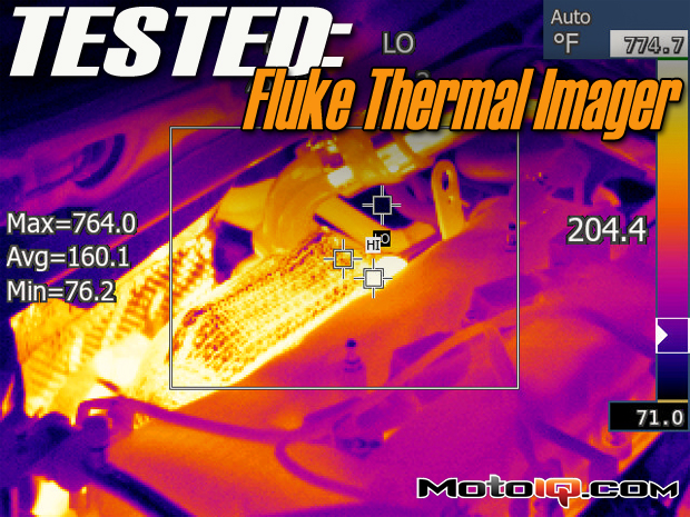
A shot of a front mount intercooler during a dyno run. In this picture, you can see there is some gradient from top to bottom. The hot air from the turbo is entering from the left and exiting the intercooler on the right.
Here’s a short video of the intercooler heating up during a dyno pull. Don’t pay too much attention to the absolute values of the temperatures measured as I did not have the emissivity setting correct for the aluminum finish of the intercooler.
My next test was checking brake rotor temperatures. If you recall from my last track day in Project S2000, the rear rotors were significantly hotter than the fronts using the good ole hand pyrometer. Now that I had a tool at measure actual temperatures, I went to my closed test course and performed a test. My test procedure was simple consisting of an out and back loop. From a stop, I would go full throttle to the top of second gear and then stand on the brakes. I then did a U-turn and again went full throttle to the top of second gear and performed a hard stop where I had an assistant use the thermal imager to measure the rotor temperatures. I performed this loop about 10 times.