,
2. Add a new equation by clicking the green plus sign.

3. Type in the desired equation. Here, we have put in Equation 3.1.A. We labeled our LF suspension potentiometer ‘LF Sensor’ when we first set up the log file in AQ1 Data Acquisition System software. Check the help file on the software to learn the syntax that the AEMData software uses for writing equations.

You can choose the data channel you want to apply the custom equation to by scrolling down on the channel list.

You can also change the drop down menu to insert other items.

4. Once this is done click “ok” and you will have a new data channel created. We added Equation 3.1.B and 3.1.C in the same manner. Here are four data channels created from one logged voltage signal:

Hopefully, this shows the power behind the math function feature in the software. Just keep this feature in mind when you are setting up your sensors before going out for a run. Recalling Tip 6- sometimes it’s useful to apply a calibration curve to a sensor when setting up the log file in AQ1 Data Acquisition System software, other times its better to log raw voltages and apply an equation to it later in the AEMData Software.
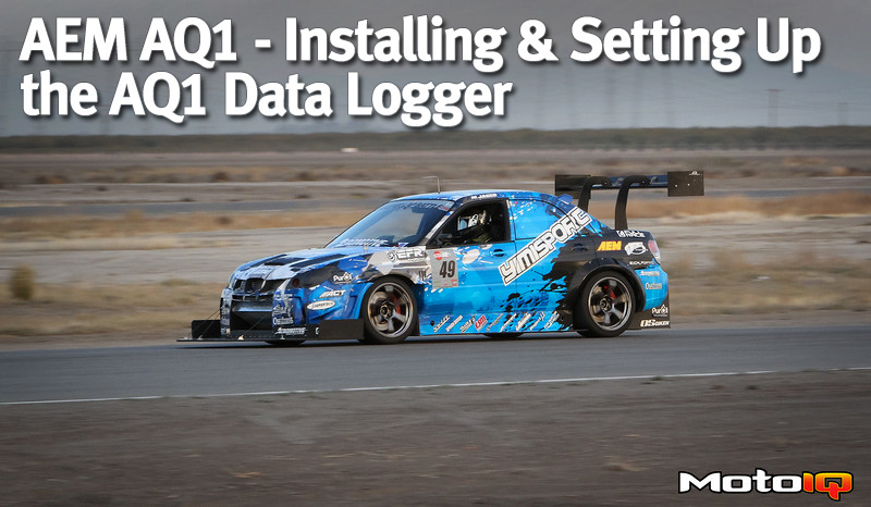
In this series of articles on the AEM AQ1, we aimed to show the power behind data logging and AEM’s new AQ1 data logger. Having used the logger for over a year now, I cannot express how invaluable it has been to the overall development of our car. Data logging is a must have tool for any racer, and with a price point of $395 and the power behind the system, AEM’s AQ1 is best option out there for the grassroots racer.
Catch up on the rest of the AEM AQ1 Technical Series
 |  |
| AEM AQ1 – Product and Features Overview | AEM AQ1 – Using Data to Develop a Car |
Sources