,
By laying out our sensor needs, it quickly became apparent to us that we would not be able to log all of the analog sensors that we wanted to on a single AQ1, as it only has 8 analog channels. We also knew that we would possibly want to add other sensors to collect data from in the future as well. Realizing this, we decided that it would be smart to create a “switchable” sensor harness. Basically, we designed two main sensor harnesses: an aero/suspension sensor harness and an engine sensor harness with two female bulkhead connectors, shown in Figure 3.3. We wired the AQ1 to a male plug, which allowed us to connect into either the aero harness or the engine harness depending on what we wanted to measure, shown in Figure 3.4. While this is not a perfect solution, it allowed us have a chance to collect aero data and engine data from the same track. Typically, we would plug into one harness for one run session, and then plug into the other harness for another session. Ultimately, splitting the sensor harness like this also allowed us to eventually add a second AQ1 so that we could simultaneously get data for both engine and aero while the car was on track, shown in Figure 3.5.


|
Tip Box #4 Constantly test your wiring harness while you are building it. Use AEM’s AQ1 Data Acquisition software to help with this. Trust me, you’ll thank yourself later that you did. |
Sensor harnesses for data loggers tend to be long and have many different connections. Each connection introduces a potential point of failure that can keep a data logger from working correctly. It is good practice to constantly check your sensor connections to the main AQ1 connector to make sure they are working. Oftentimes this can be done using a simple continuity test from the sensor wire to the AQ1 connector pin. Continuity testing is explained here.
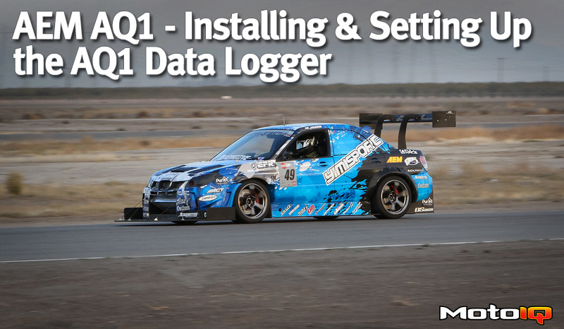
Beyond continuity testing, the AQ1 Data Acquisition software can be used to see if sensors are working using its live readout section. Superlap Battle 2015 was the first time we ran the AQ1 on our car. During the event, we found that only two of our ride height sensors were working, none of the engine gauges were data logging correctly, and the GPS signal was non-existent. Considering the amount of testing we had done on the main AQ1 harness, we were certain that there was an issue with the AQ1. We decided to bench test the unit after we got back from the event and see if there was an issue with the AQ1, or with our sensor harness.
We wired added 12V power to the AQ1 Pins 1 and 6, and battery ground on AQ1 Pin 19 via our male connector. We then used to the AQ1 Data Acquisition Software to connect to the AQ1. The live readout naturally gave voltage values of 0 for all the analog sensor channels, as there were no sensors connected to it during our bench test. We then plugged in a rotary potentiometer into the sensor power, ground, and signal locations on our male connector for the first analog sensor channel. The live readout on the software showed a voltage value and voltages changes as we turned the potentiometer, which confirmed that the first analog sensor channel was working correctly on the AQ1. We then did this to the remaining 7 analog channels, all which were confirmed to be working correctly. Thus, we realized that we had some serious wiring issues in the secondary part of the sensor harness. Continuity testing of the secondary sensor harness showed the two non functional ride height sensors had failed crimp connections on the sensor grounds. Further continuity testing showed that our GPS transponder was not wired at all, and voltage testing showed that we had wired to the wrong outputs on the engine sensors. Ultimately, diagnosing all these problems took us about a month to do, and could have been avoided if we had tested the secondary sensor harness as rigorously as we had done to the main AQ1 harness. Figure 3.6.A shows us bench testing the AQ1 unit and Figure 3.6.B shows what the AQ1 Data Acquisition Software page looks like.

Figure 3.6.A: Bench Testing the AQ1 using the AQ1 Data Acquisition Software.


