
It looks like the best place to route the hose is to go through the fender liner and up between the radiator and A/C line.

After playing around with the intercooler placement a bit more, I think the best placement will be to flip it upside down. So, the air inlet is up by the radiator on the passenger side and the air outlet is close to the throttle body. This orientation of the intercooler gives more space for the compressor inlet tube to run in that area of the oil filter and go over the top of the intercooler. The compressor outlet tube going from the turbo to the intercooler will likely go under the cross brace that the intercooler is sitting on. To make some more space, I’ll get a slim fan.

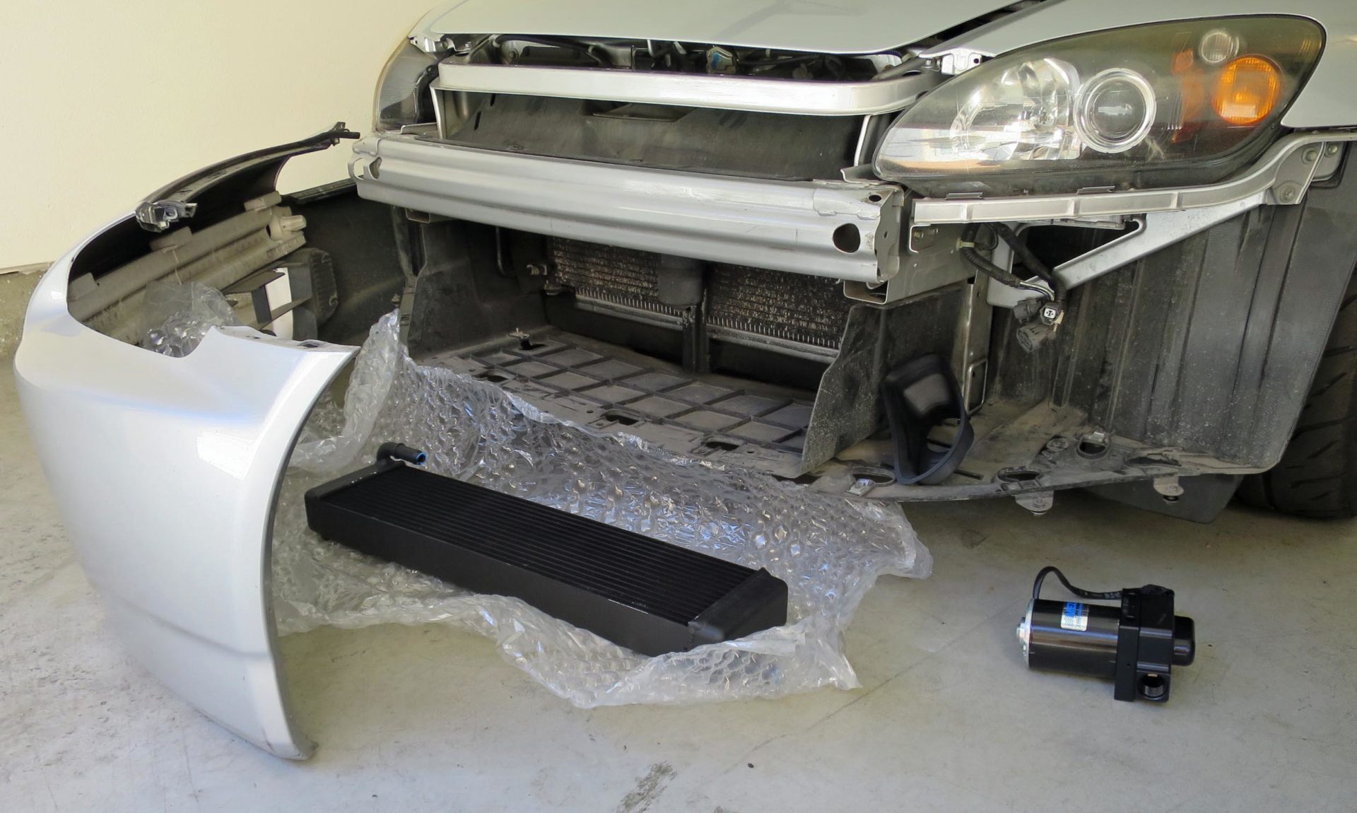
First trial fit of the Shelby GT500 heat exchanger doesn’t exactly work as the outlet hits a frame member.

You know, there’s a lot of space up there behind the bumper. And another cross brace. Honda sure did like to add braces. Check out how much the A/C condenser has been hit and the fins bent. Also, the vertical mounting bracket has taken a lot of hits too. Something that all this damage indicates though is that airflow certainly goes to these locations.


18 comments
Planning to add the ducting back, I assume? 3D print a new one? 😉
Yes, going to create a new panel. The main one will be similar to the typical ‘cooling plate’ to block off the opening from the radiator to the front bumper. It’ll be completely solid as my intake air source for the turbo inlet is now the bumper duct. I never did understand the whole cooling plate thing as that airflow path is the one for the air to the intake snorkel on the stock car and it gets some cooling air to the rest of the engine bay. I need to poke around some more to see if there are any other air leak paths.
Hello khiem, i have s2000 ap2 stock engine with kraftwerks supercharger. What oil cooler engine recommend. This kit include Intercooler front.
What position do you recommend to install the oil cooler, behind the radiator? Please give me technical recommendations to make a good assembly. I really appreciate your collaboration.
Smart use of the factory Ford parts, I bet they are the cheaper solution! I am surprised you didn’t grab the ford performance pierburg CWA50 pump or the upgraded CWA100 pump. The CWA100 is an awesome pump, I use it to keep cool 180kW electric drive unit under test.
I’ve been tempted…. and get the controller for the pump. But I already have this pump and my main concern was noise, but I ran it briefly and it seemed pretty quiet to me. I’ll probably wire it to a manual on/off switch in the cabin so that I can have it off during engine start-up to avoid straining the electrical system. My electric power steering module just failed and that’s a bit over $1000 from the dealer. I did the paper clip trick into the OBD port to pull the codes and reset the module, reset the steering torque sensor many times, but as soon as I turn the wheel after a reset, I lose the power steering. The code is for the current sensor inside the electric power steering module, so no cheap fix I don’t think. So yeah… that’s taking a BIG chunk out of my upgrade budget.
$1000 is ridiculous. You have other options. You can reduce the caster, and that will lighten the steering. You could also convert to the AP1 rack.
https://www.s2ki.com/forums/s2000-under-hood-22/gutted-s2ki-steering-rack-easy-rx7-rack-1054114/
Personally, I love manual racks… they feel so good at high speed. The new Gordon Murray Automotive T.50 is a supercar with manual steering!
And we could all use the exercise while parking. 😉
The only thing I would think is that you can likely go without the fans. The SC is not going to make much heat during times when there is not a lot of air going through the heat exchanger. If you are doing short sessions back to back with stop time in between maybe you are benefiting from the cooling between sessions. Would like to hear your thoughts.
For a road course car with higher speeds, the fans are not needed. But for auto-x, with the lower speeds and idle time staging, the fans should be of benefit.
Really excited to see the results of the Garrett turbo. I think they are often looked over.
Overlooked, parenting challenges are real.
The Garrett G-series has already proven itself in motorsports They are on a number of the fastest Pikes Peak cars along with the fastest car at World Time Attack last year in 2019, the PR 968. I am tempted to upgrade to the newer G30-660 with the 0.83 A/R housing… I think I would loose ~300rpm in spool-up and a bit in on/off response, but gain ~25whp over my current G25-660 with 0.72. But, seeing how my electric power steering needs to be fixed, that eliminated thoughts a turbo upgrade or water pump upgrade. Oh well, maybe in another couple years.
Is there a reason that water to air is becoming more common from the factory than 10 years ago? BMW, Porsche, lots of manufactures using it now. Is it related to increased efficiency with better heat transfer as compared to air to air? Or easier packaging?
Starting with the negatives, extra cost and complexity. As for the benefits, for sure is improved transient response because the airflow path from turbo to intake manifold is much shorter. Probably the number one complaint about turbocharged engines is turbo lag, so going to an air-to-water setup helps address that. They can be easier to package too. Some of the OEM setups have the air to water intercooler integrated into the intake manifold, so it doesn’t take up much more space. Also, it’s easier to route 1″ diameter coolant hoses than 2″-3″ intercooler piping which may not fit in modern super crammed engine bays. And it seems the air-to-water setup makes for a bit more consistent intake manifold air temps (slower/smaller temp swings) making engine calibration a bit easier.
Regarding IAT’s, do you think your IAT’s will be comparable/similar to an air to air intercooler for lower speeds/shorter stints? I guess for a car that spends more time on track heat soak and rising IAT’s over a session is a bigger issue than for autox?
For low speed, starting from a stop, I’d guess that air to water is better than an air to air. Especially because I’ll have fans running to keep airflow going over the heat exchanger. Ignoring that, the air to water setup has the advantage of all the thermal mass of the water in the system whereas the air to air just has the thermal mass of the aluminum of the IC. When there’s a lack of airflow, cooling of the air coming out of the turbo is just going to be due to the thermal mass in the system.
“It’s always easier the second time around, like engineering classes.”
I heard that. I had to retake Control Systems because I stupidly took it at the same time I was in Formula SAE for Senior Design and spent nearly all day and night in the computer lab running FEA sims in Catia V5. I absolutely never had enough time to do everything. Fortunately, I did really well the second time I took Control Systems because I saved all my homework and test results. The feedback helped immensely (pun intended).
Hah, dorky engineering joke!
For the location of the IC, what about in front of the frame crossbrace? It was uncomfortably close to engine when you tried it behind the crossbrace, but maybe it would fit better in front instead.
I think you could then angle it, so IC intake points down, where it will more easily flow from the turbo feed that you will run under the brace (under brace and above rack). IC output would then also point up towards TB, making that piping more direct as well.
The problem with laying it flat on top of brace is then piping on both ends are going to need to make sharp bends coming in and going out, because of the length of IC. The IC output is almost directly below TB, and similar issue on IC intake side.
Placing it in front of brace allows it to be angled, which should allow much softer curves.
Yup, I played around with it in front for the cross brace too. But I think it’ll block too much airflow coming off the radiator. Plus get hit by the warm airflow coming off the radiator 🙂 If you recall from some previous testing (https://motoiq.com/project-s2000-part-23-testing-air-temps-through-coolers-and-vents/), air coming off the radiator does seem to sneak out between the front cross member and steering rack and exit the bottom of the engine bay. I’ll probably end up cutting off the hose barbs from the IC and getting 90 deg elbows welded straight on to improve the packaging. In hindsight, I oversized the IC a bit…. a little too zealous!