In the last segment, we said that we had finished wiring everything, but that’s not quite true. There were just a couple of finishing touches to sort through and then we would be able to power up the chassis and start programming devices!
Note: This is not meant to be a comprehensive guide for how to program the various equipment on a race car. We will paraphrase and go through a lot of it. At this point you can seriously damage your car by making egregious or careless mistakes, especially once you try to turn the engine over. If you’re electronically savvy, you’ll be fine. If you’re patient and are willing to read the documentation and ask questions, you’ll be fine. If you’re a careless ass and expect to just start flipping switches and not burn your car down or kill your engine, don’t complain to me. This is the point where you might want to hire a professional. If you’re nice, I might even help!
 One of the last connectors to get sorted was the DTM-2 that would engage / disengage the contactor.
If you remember our planning article and the design of the kill circuit, you remember that we have both a cowl-mounted external kill switch as well as a cabin-mounted kill switch on the dashboard. Both of these switches must be ON for the chassis to be powered (and the contactor engaged). Either one can be OFF which will break the circuit.
 You are probably not surprised at seeing more holes being drilled. I certainly wasn’t.
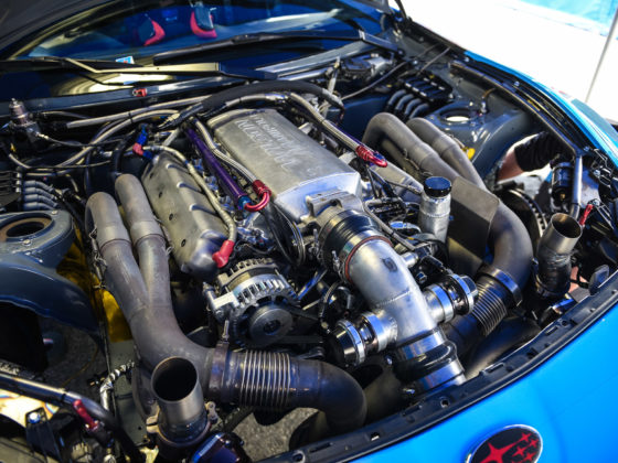
One critical circuit that we haven’t discussed recently is the alternator and battery charging circuit. Since this car is a road racing car, and it will be running for long periods of time, an alternator is still needed to charge the battery.
Toyota alternators haven’t changed much over the years, and their overall wiring is pretty simple. This site provides a great description of how to properly wire the connections to the alternator. We also talked a little bit about the alternator wiring in a previous segment.
A couple of special notes about the alternator wiring:
- The battery voltage sensing wire must be connected to the battery positive terminal, for all intents and purposes. There should be as little electrical resistance between the sensing wire connection point and the battery charging point and the battery positive terminal as possible.
- The ignition input to the alternator should be powered when the ECU is powered, more or less. For us, we will have one switch that controls all of the main vehicle electronic devices (ECU, GPS, etc)
- Originally we were going to run the lamp output (which is actually just switched to ground) to the ECU so that it would know if there was a charging failure. But, due to a few issues, and because the Haltech Elite 2500 can trigger alarms/warnings on low voltage anyway, we ended up not using this part of the circuit, even though it’s wired up. Think of it as a spare wire going from the alternator plug to the ECU. The alternator may decide it has failed for other reasons, but the pure voltage is a good enough proxy for our purposes.
The last, and most important, wire is the actual charge wire that goes from the alternator output (indicated by “B” in the linked page) to the battery. There are two critical things to note here:
- This should be a fairly large gauge wire (we used 8 AWG milspec wire) as the alternator charging current can be significant
- The charge wire MUST be connected to the battery side of the contactor
We’ve reiterated that point a few times in this article series, but it’s extremely important. If the engine is spinning, the alternator is spinning. If the alternator is spinning, it’s generating voltage to charge the battery. If you flip the kill switch, the engine is still spinning for a while. If the charge wire is on the ECU-side of the contactor, then the spinning engine and spinning alternator can generate enough voltage and current to keep the vehicle electronics powered, and your kill switch does nothing.
If you connect the charge wire to the battery side of the contactor, the spinning alternator may apply voltage at the battery, but the battery is truly cut-off from the rest of the chassis, so the electronics would immediately die.
Make sure you connect your alternator charge wire to the battery side of your kill circuit!
The hole here in the firewall is for the 8 AWG wire to pass through from the alternator.