

It’s crazy how detailed the model ends up being. Even the silly Toyota emblems got captured in the 3D model. The model is scaled and oriented to the virtual world (which is based on the real world, of course!) and then Rob uses the measurements in order to design the pylons and tabs to place the wing, taking into account the engineering requirements for thickness, interference, weld clearance, and more.
Fun fact: hardcore racer/aerodynamicsts call the stands that the wing is perched on “pylons”, because if you say “upright” it can be confusing whether someone is talking about suspension or aero.
The tabs are the feet which touch the surface of the deck lid. And, yes, in this case the pylons are mounted to the deck lid and not directly to the chassis. The corner of the lid is going to be the strongest part, and the pylons are designed to direct the forces into it in such a way that they will work effectively. If it turns out that my carbon trunk isn’t up to the task, I can revert to an OEM metal one, or add reinforcements, or both. Also, it’s much cheaper to design the deck-mounted pylons because it doesn’t require any engineering or measurement work inside of the vehicle.
Or I can pay them to design a wicked chassis mount.
After this design work, Rob meets with Johnny to make sure that the pylons are actually manufacturable and make any tweaks or changes required. If they are going for mass production, they will make a prototype for fitment. Rob can simply export a file that Johnny can use to cut out the pylons on a CNC cutting table.
While it sounds like Johnny and Rob are in business together, their businesses are distinct and separate. Rob is an integral part of the process, but Morlind Engineering is its own thing.


In the case of the pylon design for my SC300, this is 1/4 inch thick aluminum. The particular grade is chosen for its resilience to cracking given the compressive and other loads exerted on the pylons.

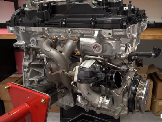
Well, we’re really making pylons, but whatever.
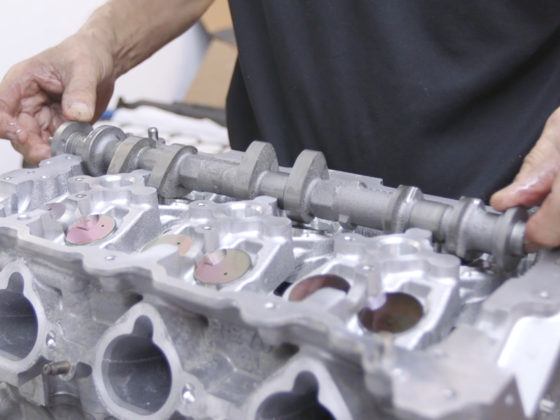
Well, really these aren’t even for my pylons, they’re for some other cool project, but I needed a picture of something, right?
5 comments
Dang, I was hoping that the paint would be use for flow visualization. Flow viz paint, and wool tufts are both cheap and effective methods to develop chassis aerodynamics.
You can’t really know what the flow is like at the back end of a vehicle without real-world testing. For example, the optimum solution for the SC300 may not be a wing, at all…but rather, a trunk lid spoiler. You can gain both downforce anb reduce drag if you design a proper spoiler. The curved surface of the SC300 rear trunk lid probably increases lift, rather than making downforce. So, there’s a huge missed opportunity by installing a rear wing only.
Personally, I would like to see more testing, and real-world verifcation before I were to commision the fabrication of a solution like a custom rear wing.
Please note, that some of the most expensive super cars currenly being produced no longer include rear wings. This is because a wing is not the optimal method to produce downforce. A diffuser/spoiler is currently en vogue because it produces downforce with very small drag penalties. A proper race car optimizes the negative lift/drag coefficient.
One should always explore as many solutions as possible before committing to one particluar solution.
I don’t want to be a complete Debbie Downer, but I would highly recommend that you use some flow viz, and install a lip spoiler on the trunk lid. (The flow viz can be used before/after to verify the solution.) A rear lid spoiler will make the rear wing and rear diffuser more efficient. Whenever you can get a two for one, that’s when you know that you are heading down the right path.
A properly designed and placed wing is the lowest drag to downforce device.
Aye, a wing is definitely the most efficient item by itself. But you can get quite significant interaction by changing the pressure distribution on a large area of the car, which is how you get crazy high lift/drag ratios like were seen in Group C racing, even with the primitive state of CFD at the time (pretty much 100% wind tunnel testing to develop those cars).
An SC300 would probably see quite a benefit by putting a small lip spoiler on the end of the trunk lid. This will encourage clean separation of flow at the rear end of the car (look at modern cars now, they all have sharp features at the very back for this reason), and at a moderate ~15-30 deg angle and ~1.5-2″ of height, it will tend to reduce total drag and add a small bit of rear downforce. We’re not talking huge downforce here, but it reduces drag at the same time, so it comes at no aero penalty.
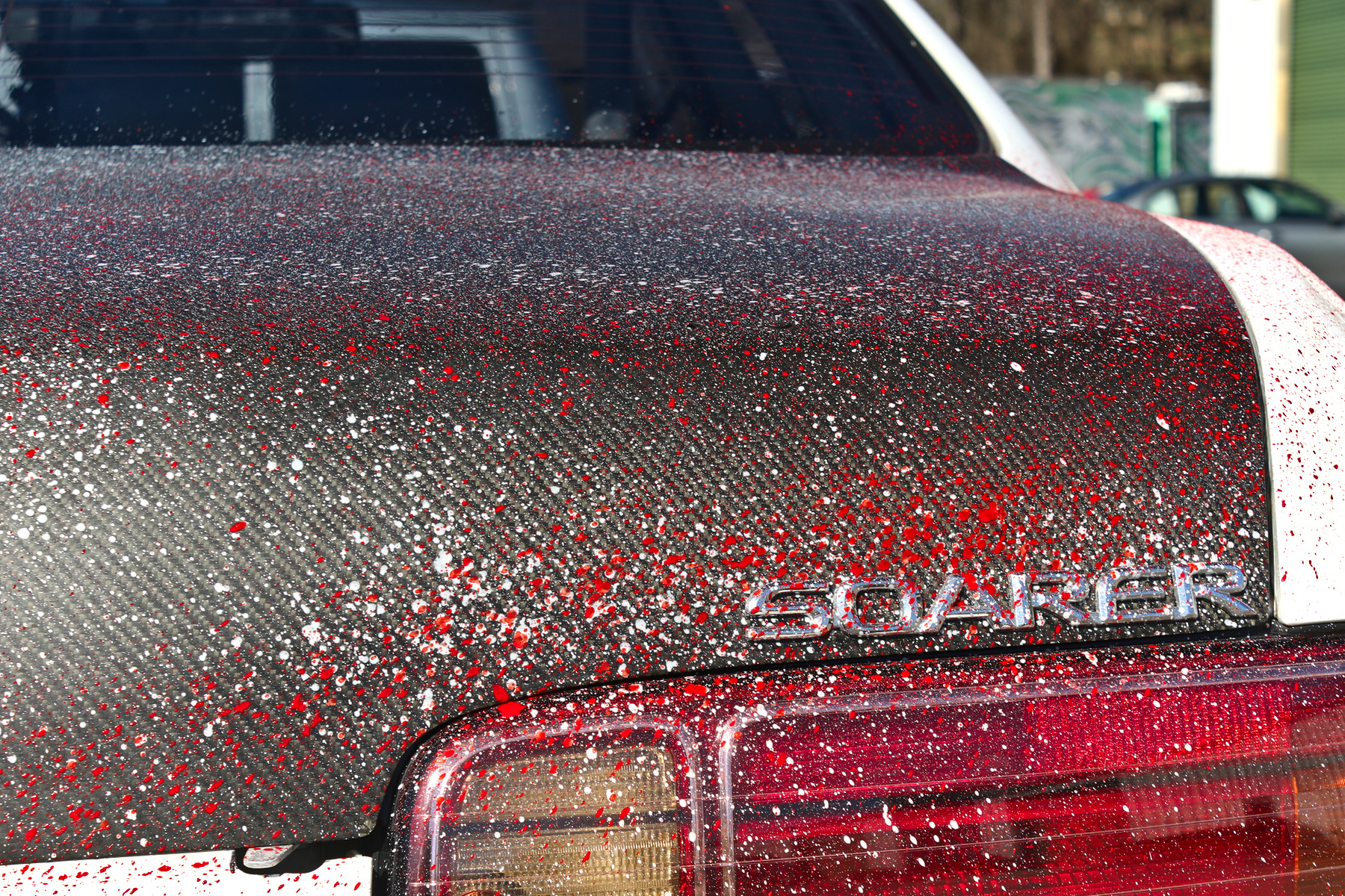
Was some type of photogrammatry used (stitched 2d photos from normal camera), or was a true 3d capture camera used?
@cmj re-read page two:
“But there’s an end to this means, I assure you. And it’s not another innuendo. I don’t think. If you look back to the photo of Rob, he’s taking a photo. In fact, he’s taking dozens of photos. You see, when you take dozens of photos from different angles of the speckled car, you can then use some really fancy computering to stitch all of the photos together to build a really accurate 3D model of the vehicle.”
https://motoiq.com/project-sc300-road-racer-part-27-joining-a-wang-gang/2/
Rob is using a regular digital camera and then stitching 2D photos together using software to build the 3D model.