Rathyna’s S13 drift car’s engine was thoroughly hammered with little compression. In our last article, we rebuilt her cylinder head with Portflow Design replacing her worn valve guides and eroded valves. When examining her SR20DET’s bottom end, we found that everything was severely worn as well. So we set about rebuilding it with forged Pistons from JE, K1 Technologies connecting rods and King Bearings.
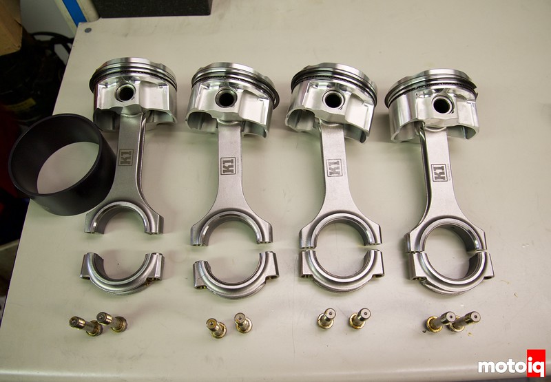
For Pistons we used JE’s shelf Asymmetrical FSR series pistons slightly oversize at 86.5mm to clean up the bore. The pistons are 8.5:1 compression and are machined from a 2618 low silicon alloy. 2618 is a tough and ductile material which is well suited to the tough abuse of drifting and turbocharging. The pistons also have an offset pin bore which helps reduce piston slap noise, especially when cold.
The piston crown has smooth contours right out of the box and does not require deburring or breaking the edges before assembly. The pistons have a 1mm top, and 1.2 mm low tension compression rings with a 2.8mm oil control ring. The rings are nitrided for long life and less chance of galling in the ring grooves.

The Asymmetrical pistons design puts more surface area on the thrust side of the piston and less on the minor side of the piston. This way the thrust loads are spread out for better wear and less noise while the minimal skirt on the minor side of the piston reduces weight and friction.

We used a full length straight walled piston pin which is better for a turbo motor because it is less likely to flex under turbocharging’s increased cylinder pressure. A flexing piston pin can grab and spin the bushing out of the small end of the connecting rod or seize on the piston pin boss which can cause failure.

The JE Pro Seal piston rings are thin for low friction and nitrided iron for slipperiness, and long service life. The second compression ring has a hooked Naiper profile which assures fast break in and superior compression sealing while maintaining low friction.
 The K1 connecting rod is designed and finish machined in the United States. Each K1 connecting rod is CNC machined from a 4340 steel forging and then undergoes core hardening and shotpeening processes to improve its fatigue strength. In addition, every K1 connecting rod is magnetic particle inspected (MPI). During this inspection process, the connecting rod is magnetized and then a magnetic flux, such as iron particles, is applied to its surface. Any surface irregularities will cause a disruption in the magnetic field, which the magnetic flux is attracted to. This attraction helps reveal any surface imperfections or flaws on the connecting rod’s surface.


19 comments
Why not OEM main studs?
For competition engines, I prefer not to use them because they are torque to yield and they stretch and take a set. They can only be reused maybe once and it’s a good idea to change them every time on a serious engine.
Mr. Kojima,
How do I get in touch with you on building a Ford V6 motor?
for the mains, did you guys use arp’s torque spec or something else? I always thought it was a bit high
We split the difference. ARP’s torque spec is too high and the threads might pull out.
What does ARP call for and what did you guys end up going with?
ARP states 80 ft/lbs we think that’s too much. We use 65 ft lbs.
No WPC this time?
No not on this engine.
Low Silicone…hehe, I hope those pistons don’t need big boobs.
stupid autocorrect
Are you modifying the upper oil pan to clear the windage tray or did you find/make a spacer? the jet nuts on my tray touch the upper pan and require me to mod my pan.
It’s weird on my FWD engine we did have to mod the pan but on this RWD engine, we didn’t.
Hi!
When would you say the HP limit is for OEM MAIN bolts?
Thanks.
//Daniel
They must be replaced every time but around 500 hp
Thank you. Did you also made an Aline bore after fitting the ARP’s?
Thanks!
We always check and in this case no. For Subarus yes 100% of the time.
Hi!
As for rods of this kind, does it matter wich side of the rod that will face front of the engine?
I was thinking of the tang grooves especially, on thrust or non thrust side. Or it doesnt really matter?
Thanks in advance.
//Daniel
No