Project Lexus SC300 Road Racer: Part 11 – Engine Bay Wiring
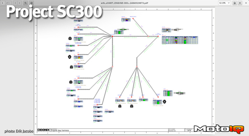
When we left Project SC300 last, we had done most of the preparation work in the engine bay getting ready to start pulling the engine harness work. For reference, let’s refer to the engine harness diagram:
The engine bay harness is fairly trivial, but it does have a few important sensor/signal circuits that we need to be mindful of. In terms of trivial power circuits, here is the list:
- Head lamps
- Turn signals
- Accusump solenoid power
- Horns
- Alternator
- Cooling fans
- ABS solenoid (future)
- Windshield wiper motor
- Starter solenoid
While we don’t expect to do much racing at night, we were trying to be thorough. And, in multi-class racing, it can be nice to have your lights on when you are coming up on slower cars. We made sure to have a power circuit to control the low beams, as well as a future circuit if we decide to run high beams (or driving lights if we do an evening/night enduro, or whatever).
Why not have turn signals? And, along the same lines, why not a horn? Plus, the horn button on the steering wheel can easily be reprogrammed to turn on some other circuit, like the headlights for flashing slow cars. Although I’ll probably be the slow car…
The car still has a wet sump (2JZ dry sumps are very, very expensive), and we had been running an Accusump previously. The Accusump has an option for an electronically controlled solenoid valve to effectively turn it on and off. This solenoid needs power. Check.
The 2JZ Haltech harness is designed just for running the engine, but makes no accommodation for the charging circuit. Alternator charging circuits aren’t all that complicated — just four wires in the case of a 2JZ alternator — but, without it, your battery would quickly go dead. We are incorporating the alternator wiring here.
The Haltech has a few digital outputs. These can be used for things like cooling fans. In our case, when the coolant reaches a high enough temperature, we will activate a digital output to go to a relay in the front corner of the engine bay. This relay will turn on the cooling fans, which draw quite a bit of current. Along with the cooling fan relay and power distribution submodule that we’ll detail later, we will also have a relay for a future ABS solenoid (if we decide to put in motorsport-grade ABS later).
I don’t intend to let a little rain scare me away, so windshield wipers are a must. The Racepak provides some neat ways to control wipers, too.
Lastly, starting the car requires sending power to the factory Toyota starter solenoid, and there is a circuit for that in this harness as well.
The rest of the circuits in this harness are signal circuits:
- Knock sensor #1 and #2
- Oil temperature
- Brake pressure
If you remember from the previous few articles, we had removed the factory ABS and used several hydraulic tees to maintain the OEM brake line setup and introduce an additional brake pressure sensor. A brake pressure sensor is a great tuning tool when you have data logging at your disposal, as it can tell you a lot about not only how you are applying the brakes, but how you are utilizing them overall.
Keeping track of oil temperature is vital for any respectable car. While it isn’t necessarily used for tuning like water temperature is (coolant temperature can be used as a scaling factor for fueling and other engine management parameters), oil temperature is critical to understanding whether a motor is operating in safe conditions or not. Alerting on it is a necessary extension.
If you read the planning article before this, you remember that the original Haltech harness did not have knock sensor provisions. The new Elite 2500 ECU supports two knock sensors, and as the 2JZ block supports two, we figured we would use them both.
 A Bosch flat response knock sensor, and some super secret special parts.
Older engines typically used what are referred to as resonant knock sensors. These were simple one-wire affairs that were pretty limited in their ability to not only detect knock, but also to be able to isolate it from all of the other noisy things that happen inside of an engine.
In a simplification, suffice it to say that a typical older resonant knock sensor (like you would find on the 2JZ) is basically a fancy microphone that is specialized to detect a specific frequency (of a knocking engine). If the engine is generating that specific knocking frequency, the output signal of this “microphone” is largest, and the ECU can detect that as knock. Pretty simple, and works OK.
There is a better option available, and that is something like these multi-wire “flat response” knock sensors from Bosch. These are very typical in modern cars, and are widely used in motorsport. Because of the former, they are a good solution for the latter — they are cheap and readily available just about anywhere. The benefit of a “flat response” sensor is that it actually can be adjusted at the ECM end for the knock frequency that you want to listen for, more or less. This allows a single sensor to be used across multiple engines, as the ECM is what is calibrated for the knock, and not the sensor. There’s a problem, though. This sensor has a hole in it, and the factory Toyota 2JZ knock sensor screws directly into the engine. What to do?


