,
 The re-assembled unit looks good.
The HWB18 also comes with a mounting tab to make securing it easy. The blue plastic pieces retain the wires and seals inside the unit. You can see the two long supply wires in a larger gauge, in addition to the small blue coil activation wires.
You might notice that there is a second blue wire. This is for a future ABS solenoid power circuit, should we ever decide to install an upgraded motorsport ABS (after removing the factory ABS).
 A ground wire is spliced together for the relay coils.
This ground will go to the same chassis location as all the other engine bay grounds, just like how we centralized the trunk grounds, too. The relay coil ground doesn’t carry a lot of current, so the standard 20-gauge wire is fine here.
 A big DTP connector is used to provide power to this assembly.
In order to make servicing easier, a large, high-current DTP connector is used for the power supply going to the relay assembly. The other side of this connector will come off of the starter power stud. We did this one “right”. The pin side is on the relay unit, and the sockets connector will be hanging off of the starter.
This is very important because the starter will see constant power at all times. Starters can draw massive amounts of current, and most cars, race or otherwise, do not use any kind of fusing or circuit protection on this circuit. That means that, as soon as the relay assembly is unplugged, you have an open connector all the way to the battery. No bueno, so a little insurance is good.
 An alternator connector mini-harness.
Toyota used several different connectors on its 1JZ/2JZ alternators. While I don’t expect to end up with an alternator using a different connector, you never know what might be available at the track (or not). Here I am using a mini-subharness to bridge a Deutsch connector to a factory Toyota style connector.
While the factory Toyota connector isn’t motorsports grade, this is easier to do than using potting compound and permanently epoxying tabs onto an alternator. It also doesn’t require removing the alternator to construct!
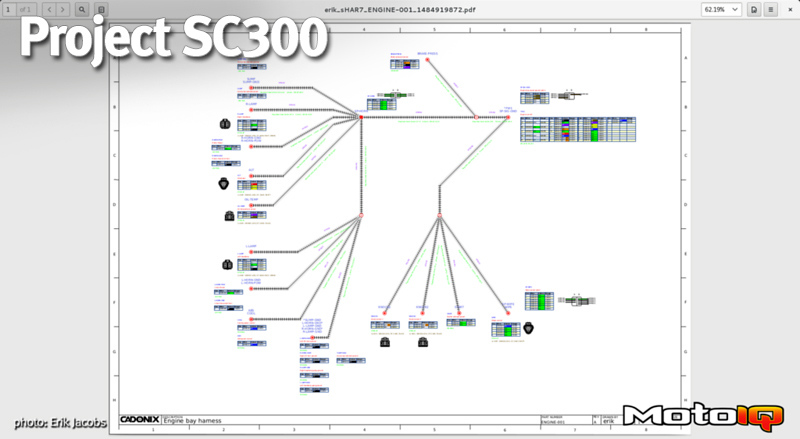
That’s about all there is to the engine bay wiring. It’s actually much simpler than might be expected. Had we been custom wiring everything from scratch instead of using the existing Haltech 2JZ plug-and-play harness, it would have been a little more complicated. There would have been a lot more shielded twisted wire for things like cam and crank sensors. There would have been a larger circular milspec connector at the firewall to accommodate the extra circuits. But, overall, you should have a great idea at this point of how to properly wire the engine bay.
Next up, we finally begin on the wires inside the cabin – the most scary part.