,
 When you’re ready to finalize the wiring, it’s a good idea to boot/glueline the terminals.
This provides some measure of environmental resistance but also ensures that debris and other things can’t accidentally connect terminals on the switch.
 You’ve seen this kind of thing before.
As with every other connector going through the firewall, we use a circular milspec connector. It is properly booted, and the rest of the harness has had heat shrink applied.
 The kill switches in the car are DPDT: double-pole, double-throw.
A DPDT switch has two circuits inside of it, and each throw (direction) of the switch results in either connecting or disconnecting one of those circuits. In the case of “killing” our electrical system, we want to do two things to make sure that it’s really dead:
- Disable / turn off the contactor which provides battery power to the electrical components (the minimum requirement)
- Ground the shutdown pin on the Racepak to ensure that the Racepak stops powering any circuits (an added bit of insurance)
If we only had one side of this cutoff circuit and if, for some reason, the contactor has “frozen” closed, we would not be able to turn off the car!
The wiring for this circuit is actually kind of complicated, but it’s almost similar in some ways to how two light switches at home can control one light. If we think about these two circuits completely separately for a moment, what would they “look” like when we have two switches?
The circuit for the contactor needs to provide +12v through the coil side to ground in order to activate it. Remember, a contactor is a big honking relay, more or less. This means that our contactor circuit needs to complete a connection between +12v on the battery to ground. A wire needs to go from the battery to one side of the coil, through the coil, to the cabin switch, then to the dash switch, and finally to ground.
Only if both switches in the cowl circuit are “closed” will the contactor be activated and the car powered. Flipping either switch and breaking the circuit will immediately stop current from flowing through the contactor’s coil and disable the contactor. This is a series circuit.
The circuit for the Racepak shutdown is a little different. To shut off the Racepak Smartwire, we need to connect one of its pins to ground. In the case of our kill circuit, either kill switch should make a ground connection. That means we essentially need to run a wire from the Racepak to both kill switches. The other side of each kill switch should connect to ground. When either of these switches “closes” the circuit, it would connect the Racepak shutdown to ground and disable it.
The tricky part here is that we need each switch to perform both of these functions, and they are opposite to one another. If the kill switches are set to ON, the shutdown should be disconnected and the contactor coil connected. If either switch is set to OFF, we need to break the contactor circuit (series) but complete one of the shutdown pin circuits (parallel).
Adding to the complication here is that all of this needs to go into our dashboard and then out to the firewall. This took a lot of mental gymnastics to figure out.
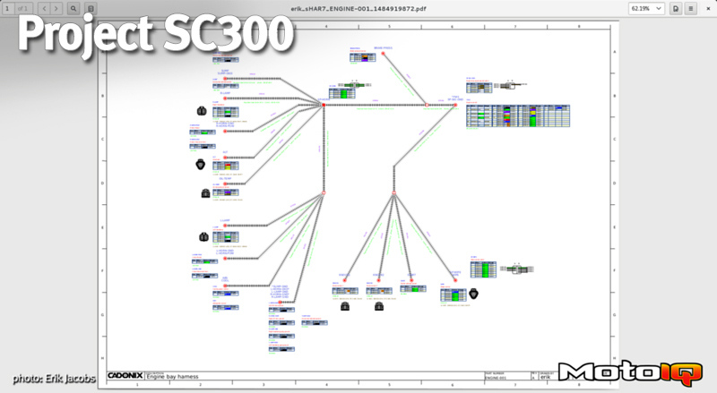
 First things first, design the circuit.
I used the schematic feature of Arcadia to draw out the circuits with the switches. I was even able to simulate toggling the switches to “see” current flow. Once I had figured out the wiring part, I then had to figure out how to actually run the wires through the car.
When we get to the cabin wiring, you’ll learn more about the complexities there.
Now it was time to return to that ugly radiator power circuitry.