
I’ve owned Project S2000 for about a decade now and it is finally time to boost it. I have a particular set of requirements and none of the existing turbo kits on the market meet them. So, I decided to design my own setup. My original Phase 2 plan was to make the S2000 similar to a Porsche GT3RS in being a fully capable track car that was dead nuts reliable and be able to drive to the track and back. I was going to do: hardtop, half-cage, and a proper driving seat. Well, things change, so now I want a big power car. It’s embarrassing that the S2000 can’t pull on a Toyota Camry. Even the new Miata is faster if you’re caught out of VTEC. Let’s call this turbo upgrade Phase 2, Rev. B.
When I bought the S2000 a decade ago, the plan was always to boost it. I still have that original plan I sent Kojima way back when. Big power is a relative term. I’m only looking for double the stock power output of the S2000. I do want maximum reliability, a stock-like flat torque curve (double the torque though for double the power), and maximum response. These requirements dictates a set of constraints on the turbo setup. Those constraints paired with my performance targets led me to design my own setup as there’s nothing on the market that meets my requirements.
My requirements: minimal relocation of components, attention to thermal management, maximum spool and throttle response, use of a catalytic converter, a mild exhaust to keep noise levels down, and 91 octane pump gas only. Due to the aim of reliability, I am leaving power on the table. The stock S2000 transmission and rear diff are not the strongest things in the world. The target power is 500 crank hp which should require about 15psi of boost given my exhaust restrictions, so we’re going lower compression which we will talk about during the engine build.

I made this sketch around two years ago with the basic concept of what I had in my head. With the reliabilty and thermal management constraints, that means a bottom mount turbo with a loggish style manifold. Bottom mount and loggish is required to maintain the stock header heat shield which protects the A/C lines, electrical boxes, and battery. Again, leaving power on the table. Also, the lower volume of the loggish manifold should have a little snappier response compared to a larger volume equal length assuming I don’t completely bugger up the design of the manifold. I’m designing the kit around the Hasport engine mount which is readily available which precludes using an equal length, 4-1 header which would hang the turbo too low. Considering all the torque the engine will be making, the Hasport mounts are also a requirement in my opinion to minimize the engine movement. Plus, I love the improvement in shifter feel with the mounts. Of course, a bottom mount turbo requires the oil filter to be relocated. To keep the charged air piping length as short as possible for maximum throttle response, I decided on an air-to-water intercooler setup. If you’ve been following our articles from the LA Auto Show over the years, you’ve noticed the OEMs have implemented air-to-water IC setups extensively.

In trying to stay as stealth as possible, I’ll be reverting back to my stock street hood. So, there will be no NACA duct feeding cold air to the turbo. However, that’s why I designed my control arm mounted brake ducts so I could use the two spots to the sides of the main front bumper opening for something else. That something else is to now feed cool air to the turbo.

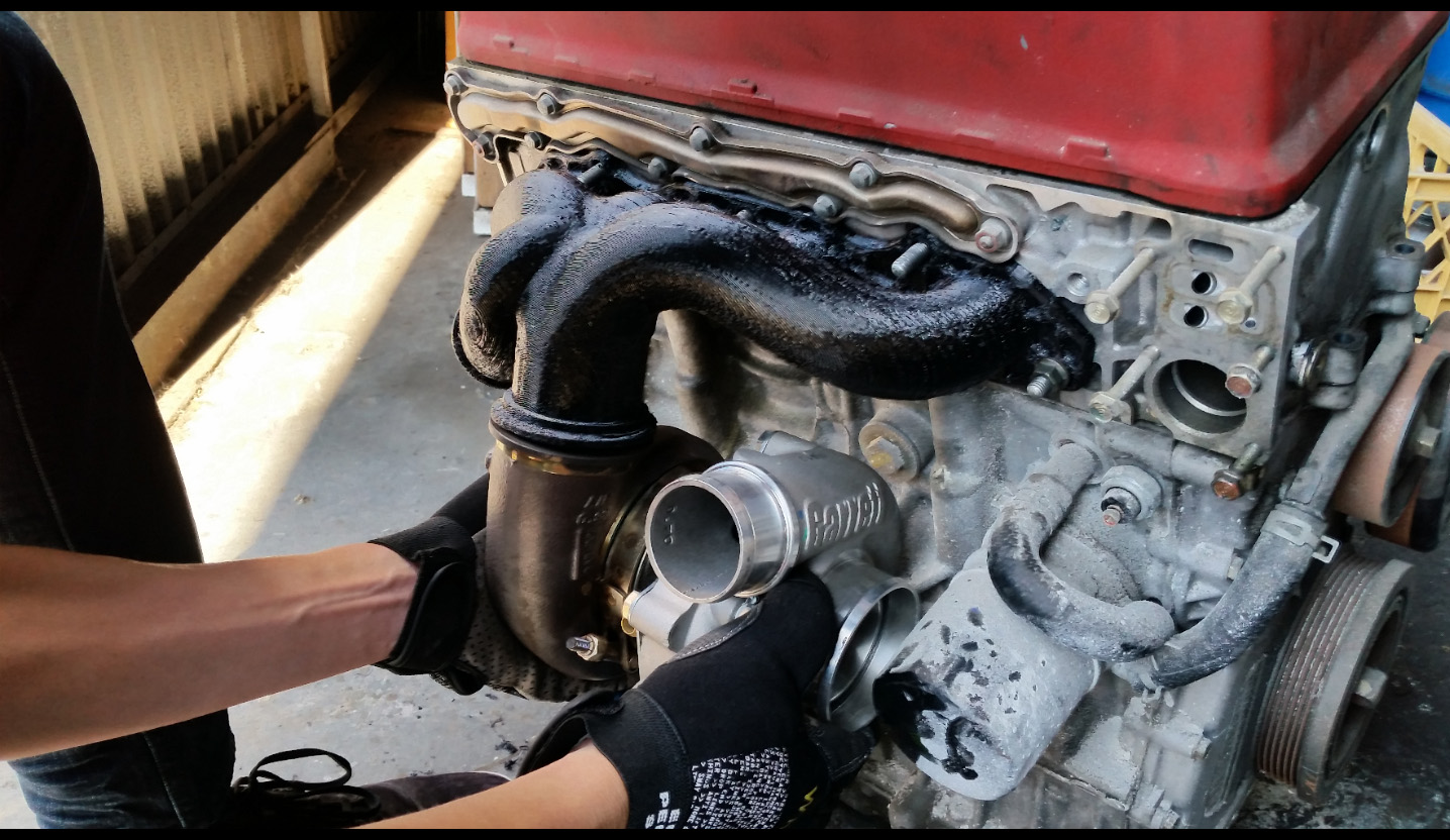
Modern design tools of 3D scanning, CFD, FEA, and rapid prototyping with 3D printing allow for very quick product development cycles and it makes designing a turbo system much easier than ever before. We like easy, so we incorporated all these tools. To get started on the 3D modeling and design of the turbo setup, we needed a model of the engine. There was a blown F20C engine sitting in the MotoIQ garage that we dragged into the office.

53 comments
2 words of advice, if its not to late: Make the shorter tubes slightly larger in diameter. Won’t give you extra power, but your turbo will live longer. Easiest way to measure how much bigger, is recycle the flower you used earlier. Fill up the large tube to the brim. Now do the same with the smal one. The flower that’s left out is your target.
Big tube cc divided by small tube cc (big tube cc minus leftover flower) = 1.xxx
1.xxx times diameter tube = your answer how much bigger the shorter tubes need to be.
If you follow that exhaust pulses will reach the turbo in more balanced intervals, creating less strain on the bearings, and a more evenly distributed exhaust pulse. Ideally you would also need to account for bends, but since its a stealth mount and packaging is key you can leave that one out.
As for the iconel: Thats fine, so long as your not running it in the rain. It’ll rust like crazy and tends to crack with rapid cooling. Then again: Your in california, so rain won’t be a regular occurrance anyway. Over here its a different story….
Thanks for the tips! The engine isn’t back in the car yet, so we haven’t done the final test fit. So still time to make some adjustments. I’m planning to get the manifold ceramic coated by Swaintech. And I won’t drive the car in the rain, which is rare occurrence out here in SoCal. I figure it’ll have enough traction issues in the dry, so no need to risk it in the wet. I am planning to use the Hondata K-Pro for boost by gear control, so i can more easily manage the traction in the lower gears. Of note, the Garrett G25 does come with a very robust ball bearing with ceramic balls and metal retainers. But will explore tweaking the diameters of runners 2 and 3. They already make a pretty tight turn upwards out of the head already…. Maybe one thing we can do is keep the cross section more elliptical instead of the current quick transition to round to gain the cross section and volume. Will look into it.
Elipticall won’t make that much difference: It still has the same short side radius that way. It’s about getting the pulses exact to the turbo, not so much the flow. But getting the same amount of volume in and elliptical shape should help the turning radius.
Another option for the bends is sectioning the bends. Wont make much of a difference so long as each section isn’t more than 15 degrees difference from the next. Air should act the same around bend sectioned like that.
And while you at it: Wrap it as well. should keep under bonnet temps down. What you could do, If there is enough material thickness, and if its just a millimeter difference in diameter, is sandblast it. But I wouldn’t risk it though.
Sorry, Kevski but going to have to call bulls##t on that. Inconel is one of the best alloys in terms of high temperature and corrosion resistance.
Nickel Alloy X-750/ Inconel X-750®
Alloy X-750 is a nickel-chromium alloy which has been made precipitation-hardenable by the additions of aluminum and titanium. Alloy X-750 has good resistance to corrosion and oxidation along with high tensile and creep rupture properties at temperature up to 1300ºF (700ºC). Due to X-750’s excellent relaxation resistance it is useful for applications as high-temperature springs and bolts, X-750 is also used in gas turbines, rocket engines, nuclear reactors, pressure vessels, tooling and aircraft structures.
Alloy X-750 Bar
Typical Mechanical Properties
Tensile Strength: 165ksi
Yield Strength (0.2% Offset): 105ksi
Elongation: 20%
Properties as described in AMS 5667 which requires that material following 1625°F/24 hrs, AC-Equalising + precipitation treatment have the following minimum room temperature properties. Hardness will lie in the range of 302-363 BHN
The nickel-chromium-iron alloys are famous materials for use in the crucial applications including pressurized and boiling water reactors, due to their outstanding corrosion resistance in steam and water conditions and resistance to chloride stress corrosion cracking. The age hardenable alloy Inconel X-750 is utilized as a spring material for fuel pellet hold down springs, fuel element divide plates and reactor scram springs and for bolting. Age hardenable alloy Inconel 718 due to its high strength and spring properties, is fit for use in fuel assembly divider plates. It also described outstanding wear resistance in sodium fast breeder reactor conditions.
The single most crucial application of nickel base alloys in the nuclear industry include the use of Inconel 600 in steam generator tubing in the pressurized water reactors. Alloy 600 withstands steam, air and carbon dioxide and hence is specifically significant in contact with steam at the elevated temperatures. Nickel based alloys have been found extremely resistant to oxidation and attack by the superheated steam and hence considerably useful in preventing the critical issues in the nuclear reactor technology. The most promising way for receiving enhanced efficiency in the power production by nuclear reactors is employment of superheated steam system where superheating is influenced by the direct supply of steam through reactor. The construction of this kind of reactor is encouraged by the nickel based alloys that have proved to become the ideal structural materials.
In addition of satisfactory performance in oxidation and corrosion conditions created by super-heated steam, effect on the mechanical characteristics of the material after the prolong exposure to the superheated steam should be taken into consideration. Particularly traditional materials are adversely hardened and embrittleed after many hours of service at temperatures around 340oC to 540oC and long duration.
Nickel based alloys are a technologically significant group of materials that are providing excellent service in the steam conditions. They are a general purpose alloy with excellent high temperature strength and resistance to steam and oxidizing or carburizing gases.
Fun Fact: Inconel (Inconel X750) was developed during the 1950s for the X-15 hypersonic rocket plane (with the first fully throttleable, restartable rocket motor named the XLR99.) The X-15 is the fastest human piloted air/space craft ever flown. It could go 4250mph (Mach 6.27) and reach an altitude of 67 miles. 5 Air Force pilots flying the X-15 were the only men outside of NASA to officially receive astronaut wings.
Your right! But I had to look it up though! It seals itself in a stainless/aluminum like manner. Looked it up, and is actually made up of Nickel and Chromium. So in a sence its related to Stainless. But I had some old Inconel headers in my hands that where rusted inside and out. And I don’t mean some oxidisation, but propper rust as in paint chipping and all kinds of crudd and pitting. Would that actually be something like a chlorine reaction?
Not sure. Most of that is copypasta. Although, I am a big aviation guy so I knew about the X15. What a machine!
I am an ME, although we had a few Nuke Engrs in my class. My Uni had a reactor on campus.
Awesome! I’d love to do something fancy like this with my car at some point. The S2000 seems to have a lot of packaging constraints that you have to deal with, and being a street car, there are even more constraints you’re putting on yourself.
I know spacing is tight, but is there a reason you can’t put the wastegate under the manifold between the turbo and the block? It seems space is tight at the rear in your car, and there might be room to save there. Of course it would make servicing the wastegate more difficult, but might clear up some space for exhaust routing etc. (of course you’re way past this point now of redesigning it)
I would also assume you’re going to add an external oil cooler of some kind when you do the relocation to help manage heat. I’m super excited to see where all of this goes. I’m always in awe of the technology we have that gets passed down making it accessible to the consumer. Printing Iconel!? Who would have thought that was possible when you got the car 10 years ago?
We tried a few different wastegate placements including between the turbo and the block, but nothing seemed to work quite as well as our final location. Again, the benefit of having the 3d engine scan and representations of the turbo and wastegate, we were able to try out a number of layouts in 3d space. Again, the fear is boost creep. Placing the wastegate on the underside of the manifold between the turbo and block, there’s not a good wastegate flow path. I’m planning to run boost by gear using the Hondata K-Pro, so likely just base wastegate spring pressure in 1st gear and ramp up the boost depending on how much traction I get in the various gears. I imagine the full 15psi of boost in 3rd gear. Well…. actually will be targeting a torque max of 350tq at the crank as that’s what my clutch setup will limit me to. The nice thing about the K-pro is I can shape the boost curve to whatever I want to get the torque curve shape I want.
Also, when my engine was pulled to be built for boost, Project S2000 (AP1) inherited my oil cooler setup. I’m actually going to revert back to the stock oil/coolant heat exchanger donut. As the car isn’t a track car, the stock oil cooler donut will be plenty sufficient. This is my old oil cooler setup for reference: https://motoiq.com/project-s2000-oil-cooling/
Khiem, can you really get 500hp from 15psi? I always thought that you could get only around 10hp/psi of boost.
Stock S2000: 250hp
15psi X 10hp/psi = 150hp
Total: 400hp
I could be easily be wrong. I think I got that number from the SCC days.
Those are rough numbers. Everyone, including myself, confuse boost pressure with “power”. We need to think about air volume and how much that turbo can provide. Other considerations are compression ratio, ignition timing, and fuel. 91 octane (and California’s is really poor) will limit ignition timing and the compression ratio considerably. I don’t see any reason why you can’t get 500 crank hp from the motor. I’m not a Honda fan, but they can be built to make good power and lots of people are doing it. I’ll stick to motors that make torque 😉 #4G63510
Boost in essence is only a measurement of restriction. You need to look at it from an airflow perspective. Getting the same amount of airflow in an engine with less boost will result a gain in horsepower. Its all about efficiency, where boost is al about restriction.
As for Fuel: Here on this side of the pond we have 97 octane. That sounds good, but it gets better and worse from here on out: Our numbering system is based on RON, where in the states its based on NON + RON. So take about 4 numbers of to get your equivalent number.
That being said: Shel V-Power is actually relatively close to 95 RON, so the same as Californian gas. And the same as our regular fuel. On the other end of the spectrum we have BP Ultimate, which consistently scores at 101/102 RON. So that would be higher.
And thats where the good news ends:
Your price per liter $0.71
Our Price per liter $1.79
Yep its that bad!
Good luck. Love the 4G63. My buddy had one that we modded heavily. We actually converted an auto to manual and put on a twin scroll. We gutted the car and it pulled like a madman on meth. Good times.
Joe, engines are just air pumps. Power is basically linearly related to air mass flow. To double the power, you double the air mass flow. To triple the power, you triple the air mass flow. So in my case, with the Hondata K-pro, my car was making 250hp crank approximately. I want 500hp crank, so I need to double the air mass flow. To do that, I need to double the air density, so I have to run a compressor pressure ratio of 2.0 which is ~15psi rounding up from 14.7psi sea level ambient. Now, if you start doing things to change the volumetric efficiency of the air pump, like cams, free flowing exhaust, test pipe, etc, it changes the power vs. boost. Your typical highly modded S2000 is running a big exhaust and often a test pipe, so those guys would make way more power at 15psi of boost than 500hp because they improved the volumetric efficiency of the air pump/engine. But for quick calcs, your compressor pressure ratio is the multiplier for HP of an NA engine. Take a LS3 which makes 430hp crank NA, run a pressure ratio of 3 (~30psi boost), and it’ll make about 1290hp.
Wastegates get too hot and need airflow.
I’m really curious as to what the cost of doing a manifold via sintered Inconel is; I have some (rotary engine) applications where that would let me do some really interesting stuff but have always assumed the price would be out of reach. Cool build!
Certainly not cheap, but also not as expensive as I would have thought…. Cost has come down quite a bit as the technology has advanced. The interesting thing with the 3d metal sintering, it’s cheaper to do inconel than SS. I was originally going to do SS because material cost is cheaper, but with 3d metal sintering, much of the cost is in the processing time and associated power consumption. With inconel, I can use a much thinner wall which drastically cuts down on the process time saving tons of cost and the inconel manifold will be cheaper or equal cost to SS.
Also, there’s basically no way to fabricate our design by hand. The wastegate flow path changing cross section shape from circle to elliptical, the merge of all the runners, etc. It would be a welding mess in the merge area if fabricated by hand.
The only alternative I’d think would work would be something like RP’d investment casting; there’s some rotary manifolds that are done that way out of 347. I guess I’ll have to get a design done and try getting some competitive quotes.
I imagine RP investment cast is in the same ballpark cost as 3d metal sintering now. Back in the day, would 3d print parts out of plastic and use them for SS investment casting. Doing a batch, maybe financially feasible compared to 3d metal sintering, but if only doing a one-off then I don’t know because of the setup cost for investment casting.
Side note, I think a G25-660 with T4, twin-scroll, internally wastegated housing in the big 0.92 A/R would be a riot for a street car on a rotary.
I’m playing with homebrew aluminum investment casting like you describe – stainless has a lot of added infrastructure. I’m in this area where I know how to do some of it, know the same ideas can be expanded to do other things… but have no idea how much it costs to have people make stuff for me.
G25-660 would be interesting but maybe too small; could be interesting actually. The EFR7670 is already riding the surge line if you push it, so the G25 pushing the surge line to the left might help early boost. The big problem is low end torque isn’t what I want out of fun car powerbands. 😉
Now, the G42-1200C, *that* looks interesting.
Dan, back in the day in machine shop class, we did aluminum investment casting. We carved out the shape we wanted from foam buried it in the sand and poured the aluminum. A guy actually did make something throttle body related for his 13b.
Have you considered the ford oil cooler adaptor used by science of speed in their kit ?
Ah, I didn’t realize that was a Ford part. Ha! Anyway, won’t work on my setup i don’t think. The SOS TS-MAX kit uses a compressor housing with I think a 2.5″ inlet. And they angle the turbo upwards a bit too to clear that Ford oil filter 90 degree adapter. On my setup, to clear the compressor inlet path, that Ford adapter would have to bolt straight to the block in place of the oil/coolant donut. Because the oil filter surface is at an angle to the oil pan, that 90 degree adapter would likely angle the oil filter into the oil pan preventing installation. Can’t really rotate that adapter upwards to the 12 o’clock position because the oil pressure sender and VTEC stuff is in the way. It could maybe be rotated so it’s about at 45deg from vertical… I am stacking the stock oil/coolant donut and oil temp/pressure sensors sandwich adapter under the oil filter. That said…. I could maybe use that Ford 90degree adapter and then attach the Canton adapter to it in order to get the oil lines to make a 90deg turn. Anyway, will have a better idea once everything goes in.
Replicating complicated cast shapes from printed inconel has to open so many doors once it’s affordable-ish. Is there any reason you couldn’t print 100 of these manifolds and sell them to spread out costs? Once the file is ready to print (and material) is it any different financially than having the mold made and ready?
There’s no real economies of scale with 3d printing. So… no benefit to printing 100. Plus, the S2000 market wouldn’t have enough buyers to pay for something like this which has a premium cost. There might be a handful of guys who are willing to pay the costs.
You mention a startup company you work for, is it automotive/engineering related? Are you no longer at honeywell?
I left Honeywell/Garrett a bit over 3 years ago. Went into EVs and learned a ton. 0-60 in 2.4 seconds will wreck some havoc on your internal equilibrium.
The new Formula E cars are pretty impressive. I have to say that electric cars have come a long way way in a very short time.
https://www.youtube.com/watch?v=3-zwveOEtMc
Back in 2011, I interviewed with a small electric vehicle company called Arcimoto, but the design is horrible. It is a 3 wheel trike design. Top speed of 75mph. 100 mile range. No doors and handlebar steering. It is really just a glorified motorcycle. Somehow, it weighs over 1800lbs. The kicker is that they want $20k for it. What???
Kind of glad I never worked with them, now. They have managed to blow $15 million in 12 years on 8 completely different prototypes (very bad sign) and have yet to build a final production candidate. The CEO trademarked FUV (fun utility vehicle.) I worked with him on a video game called Tribes. But, when EE’s design cars, that’s when things go bad.
I was kind of excited by the Elio, but that looks to be vaporware, too. I hope someone builds a high-volume lightweight EV soon. Gordon Murray (designer of the McLaren F1) is working on one. He’s got the chops to pull it off.
Cool stuff – I assume you’re going to use Inconel 625? I’d say it’s a better alloy for this than 718 due to the much longer elongation to break. It will tolerate small hot spots of high stress much better that you typically get on large delta T applications like this. 718 is stronger, but this isn’t really a strength issue, it’s more a thermal displacement problem. You also can’t analyze something like this for true peak stress with a “baby” FEA package like what you find in Solidworks.
As for Inconel rusting – hah. It’s one of the most corrosion resistant alloys known. It won’t oxidize even submerged in saltwater for decades. I’ve never had a ceramic coated manifold stay completely coated for any long length of time, so I’d probably just do heat shields personally.
Correct, 625. Agreed, Solidworks is no ANSYS , but we were pretty conservative in our analysis. Assumed a bit heavier than actual turbo weight. A bit weaker yield strength of material at elevated temperature. We followed wall thickness recommendations of a supplier based on their experience in 3d inconel printed turbo exhaust manifolds. Used standard best practices for fillet radii, etc.
I had Swaintech coating on my old SR20 cast manifold and it held up perfectly for 80k miles with a good chunk of hard use. Inconel has the same ballpark coefficient of thermal expansion as grey cast iron. SS is ~50% higher, which is why I figured SS headers has swaintech flake a little. But my old cast manifold had none of that, so I think it’ll be perfectly fine on inconel.
Most of the stress is thermal though, and I don’t know if the off the shelf Solidworks stuff can do combined thermal + static structural loading.
I’m sure it’ll be fine structurally though, as the stuff is super tough even 3d printed.
Inco 625 is a very common go-to material for rockets for all these reasons BTW.
Yup, thermal cycling will be the fatigue life factor. Typically, big fillet radius addresses cracking from cycling and constant wall thickness, avoiding thick sections.
Your right! But I had to look it up though! It seals itself in a stainless/aluminum like manner. Looked it up, and is actually made up of Nickel and Chromium. So in a sence its related to Stainless. But I had some old Inconel headers in my hands that where rusted inside and out. And I don’t mean some oxidisation, but propper rust as in paint chipping and all kinds of crudd and pitting. Would that actually be something like a chlorine reaction?
Inco 625 is totally resistant to chloride environments. It exhibits no stress corrosion cracking, so by default it will have no exfoliation corrosion.
It’s pretty hard to find stuff that it can’t resist honestly.
If you had flaking corrosion material in a header – sorry, it definitely wasn’t Inconel. Nothing in automotive exhaust could do that to Inconel.
I agree with the most recent comments regarding Inconel. I don’t know of any Inconel alloy that will readily oxidize (rust), but there are major differences in the Inconels. I think that Inco 718 alloy is about 20% iron and is age hardenable, but 625 has less than 5% iron.
I love the work that you are doing with additive manufacturing, so I am not suggesting anything different. But you may want to know that there are companies that can make just about any shape inco 625 ducting that can be drawn. However, the tooling can get very costly. These guys do the engine bleed air ducting for the F35 fighter aircraft.
https://www.arrowheadproducts.net/products/metals/
I know you did mention that the CFD was just a rough analysis, but I’d be wary of Solidworks Flow Sim. While it can work with enough time and effort it is really limited in its meshing, turbulence modelling, solvers, and practically everything that matters for CFD. If you have the time (and perhaps this isn’t the case which I can understand) I would highly recommend looking into OpenFOAM. It is free and although very hard to use very powerful. Its also not a ho hum software either, its used by many F1 teams as well.
Other than that love your articles, you have a good balance of technical rigor and application which is hard for a site with a viewership with such a wide range of technical background.
I used FLUENT for CFD and CATIA for CAD/CAM/FEA in school. Wasn’t too hard, put the parts weren’t too complicated. I think ANSYS bought FLUENT, though. CATIA FEA for assemblies was really good.
Of course, you absolutely have to know what you are doing and recognize the limitations on the simulation. We validated our parts. I spent months getting it perfect. Eventually, it was very accurate, but that was after learning from a lot of mistakes. We would take over the entire computer lab on the weekends running sims. The parabolic mesh got great results but took forever. We practically lived in that lab. One grad student actually did live there for a little while. He slept on the couch in the lounge. Sometimes, I wondered if that guy ever saw daylight that term.
Most important thing to remember is the old adage, Garbage In=Garbage Out
Solidworks Flowsim and FEA were essentially worthless. Solidworks is fine for CAD/CAM but I never got realistic results from the simulations.
I was just looking at OpenFOAM a couple days ago actually. I’m working on another project, just doing some research. Pretty basic pipe flow stuff. I’m trying out SimScale and it’s good enough for my purposes.
Rami, much appreciated on the comment. It’s always a challenge to find the right balance to make things technically/scientifically interesting without getting boring or too far over peoples’ heads.
I currently own an ap2 with an OG Greddy Cast turbo setup.
Ive slowly updated all the supporting mods (fuel System,IC, Oil Cooler and filter relocation, ECU, Etc..) but on the 2020 to do list is to replace the manifold and turbo.
Will be watching this build closely, but Ill be the 1st to say Im someone that would be interested in what it would cost to purchase a manifold post all your R&D, or to find a facility to actually 3D print a product like this if you were willing to allow the design to be replicated My car is also a 3 season street car (get 10k+ Miles driven on it each year) that attends 5-7 track days. I dont have the time to personally design something like this but im very interested in something like this with the exact same turbocharger setup (seen them at PRI)
Andre, I’ll get a hold of you when I’m ready to get the manifold printed in Inconel 625. That’s probably about 3 months away. The manifold alone will be in the ball park of a basic complete turbo kit. Keep an eye on that OG Greddy manifold. I’m sure you’re aware those are very prone to cracking.
Yeah. This thing is 10+ years old at this point. If it dies, it dies (Drago Voice)
Project is still alive! Work/life have a way of slowing down side projects. I’ll let you know how much things cost when I get there for the manifold.
great info!!! im down to be one of the 1st person to buy it if you do ever put it put it in sale.. ive been actually debating between fullrace short ram vs ptuning but im interested on how yours will come out!
Project is moving slowly… but still in progress! We test fit the plastic manifold on the engine in the engine bay recently. Everything JUST fit! Including underneath the stock black heat shield. But we’re making some design changes to optimize now that we know how much actual space we have relative to the frame rails in the engine bay. Hope to have the updated manifold design completed shortly.
Keep in mind the manifold alone will cost as much as other complete kits. I’ll email you though once I figure out the actual cost. Overall setup, while I decided to go with a custom air-to-water setup, and air-to-air would be much easier and cheaper. I can certainly have two of the manifolds and downpipes made however.
Any updates on the project?
I am wondering,any chance you could send me the 3d scan file of the G25 turbo in order to check fitment with RHD S2000… i highly doubt it would fit but i rather find out using a 3d printed version than a real life garrett.
Good luck with your project.
I actually was working on a new revision of the manifold today. Making some tweaks to improve clearances and whatnot. Not sure I’m cleared to send the scan out without permission from Garrett. Have you tried contacting your local distributor?
Also, my scan was of a G25-660 with the internal wastegate housing. I can tell you right now that variant won’t fit, you’ll need to go external wastegate. I looked at a picture of a RHD S2k and any turbo setup that fits under the stock black header heat-shield should work. So my setup will work 🙂
Still need to figure out the exact EWG plumbing route, but that will have to be determined in real life after I have the manifold made. I’ve gotten as far as making sure the EWG fits with the downpipe. Just not sure how creative we will have to get with the wastegate dump tube.
I ll try to source one for a mock up maybe, i am waitting to see your finished product!!! Thank you for your time!
You can also take the measurements off the of the Garrett website to make a rough model.
I must missed your last comment, yeah rough model in such a tight space will not cut it in my opinion.
Anyway, since you used the iwg model for scanning, could you tell if it could fit on a top mount manifold? I am worried that downpipe will not fit since the iwg model seems to have more length.
The length will not be an issue with the IWG. On s2ki.com, there’s the thread where the guy fit an IWG EFR7064. It looks to hang the actuator off the side of the comp housing similar to the G-series. He did have cheater bend on his downpipe to get it to fit, but it didn’t seem to hurt performance much. The only question is what stuff on the RHD layout may interfere.
Hey Khiem, are you able to share the 3d scan?
I’m trying to 3d print this exact turbo for mockup purposes and can’t find any dimensions or files to do so.