,


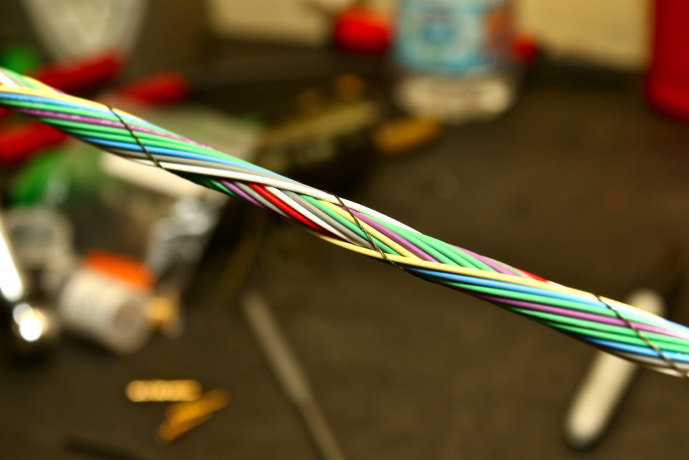
Lap splices are properly crimped and glue-line shrunk.
Quality ECUs like the Haltech Elite 2500 have dedicated signal voltage reference for various sensors, as well as an isolated signal ground for ground reference. Since we were adding some new signals, we needed to tap into these existing +5V and signal ground lines. On this side of the sub-harness, we are actually splitting signal ground and +5V reference to go to the spares connector. If we ever add additional sensors they will need to use the same signal and ground reference as all of the others on the ECU. In other words, every sensor that is attached to the ECU should be using the ECU’s +5V and signal ground.

The DTM connectors on one end of the ECU bridge.
Here are the ECU and spares connections. The other side of the harness will be stuck into the Haltech’s A and/or B connectors. There will also be the small leg for the CAN bus as well as the wheel speed (SPI – pulsed input) leg.

The completed ECU and spares legs, nicely shrunk and glued.

Haltech’s ECUs use an AMP Superseal connector, which uses a different crimp tool, as it has standard “folded”-type crimps.