,

Sometimes it’s nice to draw the stuff by hand with pencil because it lets you make a few changes quickly and easily. This diagram could’ve then been drawn into Cadonix Arcadia as a schematic, just like we did for the cowl kill switch, and simulated to ensure electrical functionality.
As you can see, the blinker is a little complicated. It uses a SPDT switch (single pole, double throw). We also chose a switch that had LED lamps in it to indicate when one of the circuits was active. Who wants to accidentally leave the blinkers on?
+12V is fed out of the Racepak into the dash connector, and then split out to the blinker switch. When the switch is activated in either direction, it completes a circuit back to the Racepak, which tells it to actuate either the left or right blinker. That also completes a circuit to power the little LED lamp in the switch. Pretty nifty, and one more circuit down.
The steering column motors were a little trickier, but only marginally so. One of the nice things about a DC motor is that it usually is happy to spin either way. And the way that you do that is by simply reversing the polarity of the voltage applied to its connectors. +12V and ground one way, and the motor spins clockwise. +12V and ground the other way, and it spins counter-clockwise. But how could we accomplish that in our circuit? A momentary DPDT comes to our rescue (double pole, double throw). Momentary just means that it completes the circuit only as long as you hold down the button.
Here again we apply a constant 12V to one side of the switch. Take a look at the one labeled “up down”. If we push the switch one way, it provides a path for current to flow from terminal 2 to terminal 1. Terminal 1 is connected to the dashboard connector, and the other side of the dashboard connector goes out to one terminal on the up/down motor. The other terminal on the up down/down motor comes back to the dashboard, and is connected to terminal 3 and 4 of this switch.
You see that when the switch is pushed “left” in the diagram, it also completes a connection between terminal 4 and terminal 5. This allows for the current flowing to find a path to ground. If we trace this again, for pressing “left”:
- +12V into dashboard
- +12V into up/down terminal 2
- +12V connected to terminal 1
- Terminal 1 goes out of dashboard pin 4 to motor “+”
- Motor “-” comes back to dashboard pin 5
- Dashboard pin 5 goes to up/down switch terminal 4
- Pressing “left” connects terminal 4 to terminal 5
- Terminal 5 is connected to ground, offering a path for current to flow from +12V to ground through the motor
Now look at what happens if you press that same switch to the “right”. Switch terminal 3 is connected to the motor’s negative (-) terminal! So, instead of current flowing from the positive to the negative side of the motor, it flows from the negative to the positive side of the motor, which is basically switching the polarity!
We follow the same exact pattern for the in/out switch. Depending on which way you press the switch, you are effectively applying +12V and ground “forwards” or “backwards” across the DC motors in the steering column.
You might notice one drawback to this setup. We are applying constant +12V power to these switches, and completing a powered circuit that draws fairly significant current with a switch. This is not really a great practice, because it results in internal arcing when the switch circuits are completed or broken, and accelerates the wear on the switch. But these are automotive-grade switches that are designed (somewhat) for this purpose, so they will probably survive.
Also, a special thanks goes out to Paul at Carling, the company that makes the switches we used. The LED version of the SPDT switch was not available anywhere online, but he was able to provide us with one. If you were going to do something like this on your own car, I would advise using all toggle-style switches and rigging your own LEDs. It’s really not that hard, and automotive panel-mount LEDs are easy to find in a variety of colors, sizes, and designs.

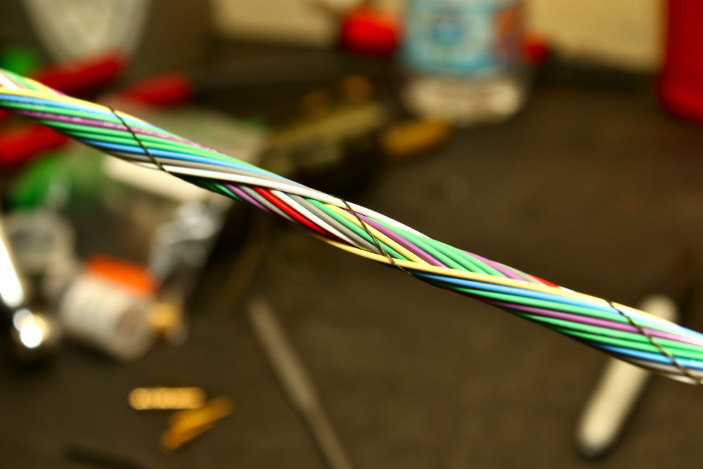
Tom is twisting the leg of the main cabin harness that will go to the rear bulkhead.
This is probably one of the longest single runs on the car. It doesn’t have a lot of wires in it, as it’s only for a few pumps and lights, but it does go from basically the front right A pillar all the way to the rear right bulkhead. So that’s a lot of twisting and tying.

Sometimes you use simple techniques to get the job done.
Here we have marked some green wires with two dots. We have a lot of “legs” on these harnesses, with wires going everywhere. When you’ve got several wires of the same color that are coming from different sources and ending up at the same destination, it can be hard to figure out which one is which for the purposes of figuring out what pins to put in which connector holes. The dots help make it easy to know where the source is, and then a multimeter in connectivity mode helps you finalize which wire is which to go where. Sometimes the simple tricks just work.