,

We didn’t quite have the right tool, so a little adjustment with the pliers ensured that everything was in order.

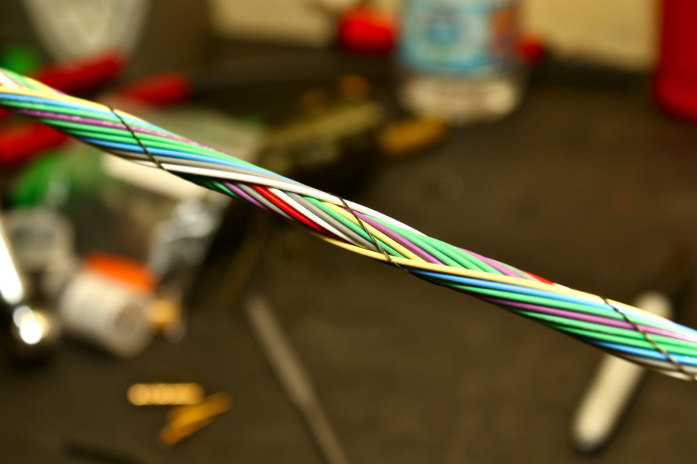
CAN wiring should be twisted pair.
CAN stands for Controller Area Network, and Wikipedia has lots of information about it. It has become the defacto standard communications mechanism for electronic devices in vehicles around the world. A large number of devices can be attached to the same CAN bus, which makes it ideal for multiple controllers trying to talk to each other without complicated wiring. We’ll go into some more specifics of how CAN works when we start programming devices. For now, the electrical aspect is what we’re concerned with. So why the twisted pair?
Electrically-speaking, the CAN bus has a high signal wire and a low signal wire. CAN requires and involves nothing else. Many CAN connections feature four wires, which might lead one to believe that there are additional things required — there are not. Commonly a power and ground is run with the CAN cable for devices that then receive power that way, but the CAN specification does not include either power or ground. It’s just two little wires. But they are important.
HIgh and Low have to do with the electrical aspect of the signals sent along the CAN cable. In computer-land, everything is binary. You have 1 (on) and 0 (off). On a one-wire communications line, you would traditionally raise the voltage to high (generally 5V) for representing a 1/on, and lower it to ground or 0V to represent a zero/off. One wire signaling is prone to errors due to noise and interference.
In a two-wire system, you have an opposing operation on the second wire. So, when you are transmitting a 1/on, you would raise the High side to +5V, and lower the Low side to -5V. This has all kinds of benefits when it comes to signal noise and reducing errors from interference. If you remember anything from high school physics electricity and magnetism, you remember that current passing through a wire generates electrical fields. By twisting the two wires together, you further help to ensure that they are not influenced by other signals and do not influence one another.
MilSpecWiring handily sells pre-twisted 22AWG cable in Yellow/Green, which is a standard color combination for CAN In motorsport applications. We have three sections here. One is to go to the Haltech CAN hub. Another is to go to the Autosport Labs Racecapture Pro/2 logger. And the third is a spare of sorts, which will serve two functions. One job of the spare connection is to provide a port to “sniff” the CAN bus for troubleshooting. You can plug a reader in and see all the messages going back and forth. Additionally, from an electrical perspective, sometimes you need to add termination resistors to the bus for devices that cannot themselves terminate. The connector makes it easy to just plug in a resistor if needed.

All of the CAN High and Can Low signals originate at the Haltech ECU, so they are spliced together.
Yellow is generally used for high and green for low. We are splicing all the yellows together, and then all the greens together, and the other side will go into the ECU’s Hi and Low pins, respectively.

Here’s our nice CAN legs.
You’ll notice a brown wire with a connector on it. Haltech passes signal ground through their CAN cables, so we did this just to stay consistent with their wiring. They also pass +12V switched power, but we knew we did not need that, so we omitted it. And it would have been a pain in the butt to source.