,

Even with all the dots and labels and other pre-emptive techniques, it still ends up boiling down, often times, to testing with the multi-meter.

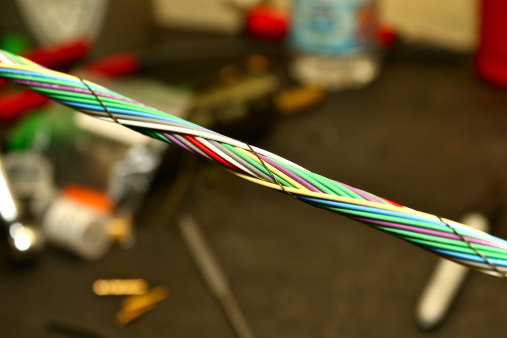
After many, many, many hours, all the connectors are on, and the cabin harness is almost complete!
Hopefully everything is the right length, because there’s no real turning back now. When you design your harnesses, make sure you add a good margin of extra length to your runs. You can always trim wires shorter. You can’t easily make them longer.
Well, I mean, you can, but it involves ugly splices and nobody wants that.

Haltech uses an interesting Tyco connector on the WBC-1 wideband controller.
In order to get the pins out, you need a special removal tool. But we didn’t have the special removal tool. So we made one out of welding wire, and a hammer, and patience. Since we were not going to use any of the WBC-1’s provided harness, we de-pinned the entire connector, and then ordered up some spare pins from Haltech to make our own. You know what crimping, stripping, and pinning looks like. No need to show you again.

The factory Toyota brake pedal switch.
Toyota already provided a super convenient method for actuating the brake lights. There’s already a switch on the brake pedal bracket and it’s all super factory goodness. Except that I needed to run my own wires. Instead of fighting with trying to shove wires into the switch at the end of the cabin harness (if the switch ever died), I decided to make a simple sub-harness.

The Toyota side of this deal has bladed-ish pins, and I was able to mangle the 0.250” terminals to shove them hard enough onto the brake switch that they were not likely to budge.
Tucking a little bit of 1/8” heat shrink over each terminal ensured electrical isolation just in case. While there are only two wires here, a little bit of twist and shrink couldn’t hurt. The brake switch actually has four pins. This is because, on the SC300, it is used for both brake lights and disabling cruise control (if it is engaged). I wanted to complete a circuit to ground when pressing the brake pedal. If we think about this, when the brake pedal is in its resting position, the switch is activated. The brake pedal rises to press on the switch. When the switch is pressed, the connections are open. When the switch is released, a connection is made.
I chose two terminals that became connected when the switch was not depressed. In this way, pressing the brake pedal (which released the switch) could complete a circuit from the Racepak Smartwire to ground. That’s what would be used to turn on the brake lights.