,
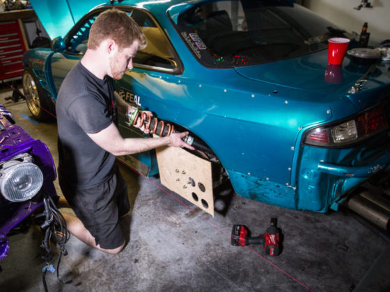
 Here you can see what it looks like once we inserted the larger connector through the panel.
We would need to repeat the notching process on the other two holes. Keeping the notches at the top of the hole means all the connectors can be easily inserted the same way. You might be wondering why there is only one notch despite there being three retention pins. You can insert the bottom side of the connector through the hole at an angle and get the bottom two pins through, and then rotate the top in through the notch to get the third through.
 Here Tom is adding the notches for the other two holes.
In addition to the notches, we would also need to accommodate the mounting of the connectors via their flanges.
 Before you start drilling/enlarging holes and modifying things, make sure that the bolts you use on the inside of the flange are small enough to allow the mating connector to fully seat and lock.
The circular milspec connectors don’t just plug in. The retention pins on one side are mated to a slot in the other side of the connector, and then the connector shell is rotated to lock things into place. If your bolts are too tall, the shell will not be able to fully rotate down into its locked and seated position. Ask us how we know…
 We continued along the inside of the passenger-side floor area, utilizing the factory Toyota harness mounting locations as available.
Simple zip ties were used. There are two bundles here. One is the main power bundle for the lights, fuel pumps, and fuel level sensor. The other is the wheel speed sensor harness for the rear two wheel speed sensors.
 The rear bulkhead connection used both a DT and a circular milspec.
Since we only had 12 connections, and since we had higher power requirements due to the fuel pumps, we used a less expensive DT. The circular milspec is used for the wheel speed sensor harness.