,
 We then shrunk the individual bundles for each switch.
The P7 switches actually have two circuits inside. One is normally open and one is normally closed. This is why you see four pins.
 Here’s everything buttoned up.
This is the one time on the car that we had to use solder. The tiny little wires were soldered to the tiny little switch pins and then covered in non-conductive RTV to help protect them as well as to prevent any accidental short circuits.
All the wire bundles are neatly zip tied onto the loops which themselves are epoxied to the steering wheel.
 Here’s the finished product ready to be installed into the car.
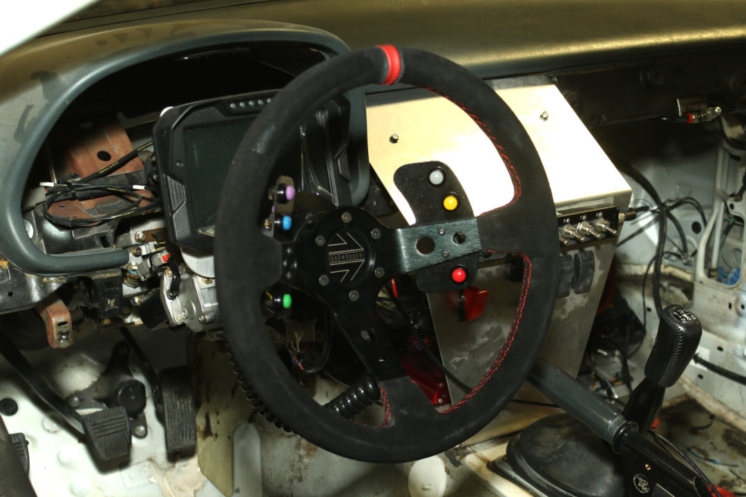
We wanted a quick release for the steering wheel. But the quick release was designed for 6-bolt mounting. This meant that we also needed a steering wheel adapter to attach to the Toyota/Lexus. Fortunately all of these parts are easy to find out there on the interwebs.
 And there you have it! A few labels from our Dymo XTL labeler to identify which switch is which and we’ll be ready for action.
You can’t see it, but the DTM-12 that connects the steering wheel harness to the cabin harness is attached to the dashboard. Ideally the steering wheel harness side should itself be strain relieved so that the movement of the curly cord doesn’t yank on the pins in the connector.
In the next segment we’ll finally power this thing up!