

The upright is a thing of beauty! In the last two pictures, you can see the extreme steering angle developed which approaches 70 degrees with no wheel wobble or sticking caused by overcentering.

You can see the low profile and minimal offset we have in the upright geometry which will reduce the jacking caused by the steering going through the huge, nearly 70 degrees of lock and subsequent tilting of the wheel. An issue with drift cars is that the steering angles produced are so extreme, problems caused by wheel tilt, bump steer and Ackerman build up at close to full lock becomes an issue that produces handling problems that you would never even bother to think about in a conventional race car. With our team, when we started to look at front suspension geometry focusing on what happens at high steering angles and controlling what the tires are doing in this state versus the typical angles you see in road racing, the better and better we have been able to get the car to work.

With the car put together, it was time to test at Willow Springs International Raceway. Willow Springs has the Balcony drift facility which is basically several acres of flat pavement. When we go testing, we usually leave the car’s bodywork off so it doesn’t get messed up and so we don’t have to be so careful loading it up. It also enables us to get to the suspension and adjust it or modify things many times quicker since nothing is in the way. Alignment is super easy when you can just reach down to get at things. The car kind of looks like a dune buggy this in testing mode!
The Balcony is big enough for us to reach the top of third gear. This isn’t fast enough to simulate a typical Formula Drift course but we can get a basic idea of how the car would work.

7 comments
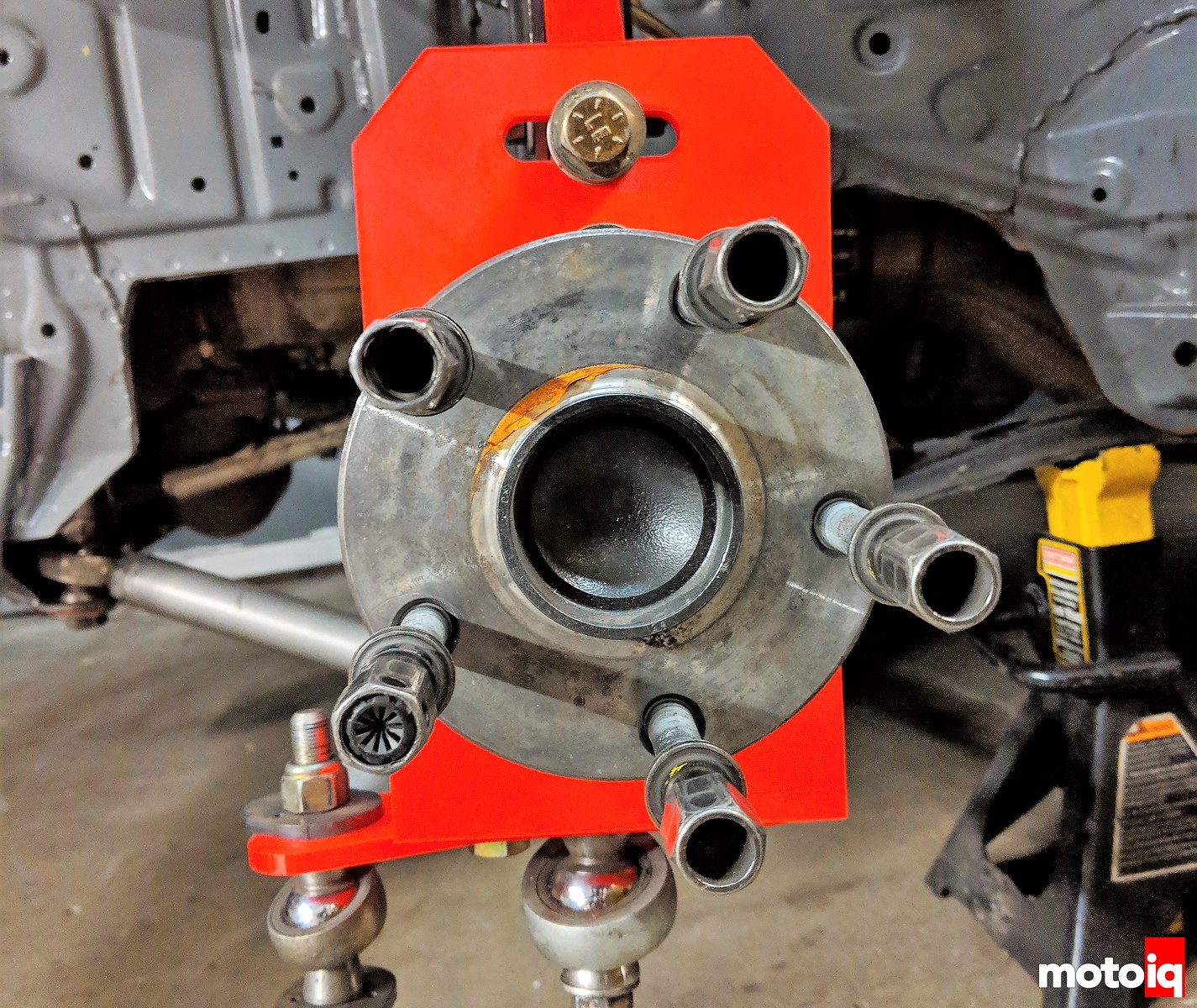
Nice setup, but just wondering about one thing: Why all the holes inside of it all? Wouldn’t it just be easier to make it in a flat panel without the holes? It’s probably done to reduce weight without a big compromise to strength, but i can imagine rubber debris is getting slewn in there?
Some of it is to reduce weight and also to get to the bolts holding the hub in. Debris can fall out the bottom easily and we have not had a problem with that issue. We design it to be pretty strong and the suspension links are the fuse in the design. We have stress riser failure points built into the arms so they will fail before the upright and chassis. This way we can repair the car in the allotted 5 minutes.
Ah right! I couldn’t see there where bolts inside, but that makes sense. Good thinking about the arms. Way less hassle to replace!
Cool. This validates my ideas on optimization of a drift car. Namely, the reduction of caster and Ackerman.
I learned a long time ago that caster (and dynamic camber gain) as the ‘secret’ to good turn-in ability. When you analyze your own footwork, you can see that your ‘outside foot’ digs in on the inside edge to initiate a turn. The same thing needs to happen with the tire footprint. The tire needs dynamic negative camber gain on the outside wheel, in order to initiate a turn to the inside. You can do this with SLA suspension, or by dialing up the caster on a strut equipped vehicle.
But, the same thing that helps a race car, works against a drift car, specifically because of the extreme steering angles. The driver has to fight against the wheel when the caster and Ackerman are high. Also, the drift car isn’t ‘turning’ in the conventional way, so you have to undo what works on one car, in order to optimize the other.
That is not how it works.
BTW, nice part design.
Totally unrelated to the knuckle design (which is really awesome), I noticed that you’re using the Hyperco articulating spring perch. Did they make a tangible difference? I hear they need frequent rebuilds.