

In our last story, we were redesigning the steering knuckle/upright for the 2019 season on Dai Yoshihara’s Turn 14 Formula Drift BR-Z. Our design goals were to keep the tires flatter on the ground with reduced camber change over the cars turning lock, increase the amount of steering angle, improve self-steer, quicken the steering ratio, reduce stress on the power steering pump and reduce chassis geometric weight jacking under extreme steering angles.
In part one we had made a parametric stick model of our upright with all mounting and pivoting points represented and made a simple adjustable 3D printed part that we could fit on the actual car, cycle and adjust to quickly experiment with configuration changes in real life as a tool and visual aid. With this, we quickly settled on the geometry we wanted on the real part.

With all the hard mounting points and pivot locations identified, Chis Eimer of Eimer Engineering went ahead and drew up the upright fully in solid works. You can see some of the cool stuff in the design like the different pills used to adjust the Ackerman angle by changing the tie rod pick up point.
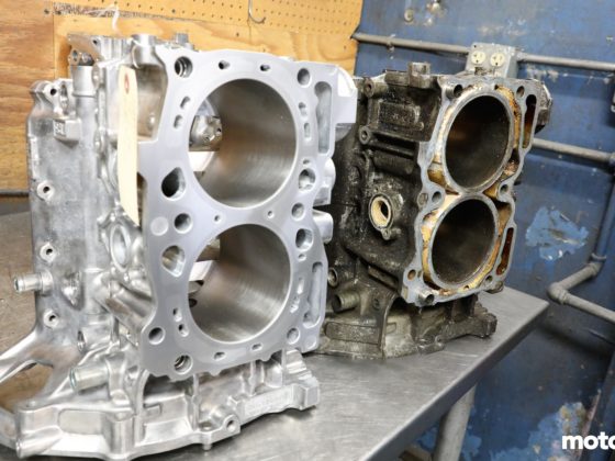
The upright is made of 3/16″ thick 4130 chromoly plate. It is arranged so the upright is hollow in construction with a large cross-section so it ends up being much stronger but lighter than the stock part. The plate is laser cut into shape and tig welded together. Note how the pieces interlock to make the assembly of the part easier and more precise to fabricate.

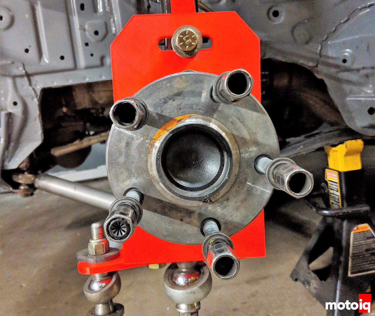
Here is the actual fabricated part as installed on the car. You can see its large boxed cross-section thin wall construction. We feel that our method of building the uprights on this car is somewhat innovative, at least in the drift world and we can deliver high strength, accurate but lightweight parts with very little tooling cost.

7 comments
Nice setup, but just wondering about one thing: Why all the holes inside of it all? Wouldn’t it just be easier to make it in a flat panel without the holes? It’s probably done to reduce weight without a big compromise to strength, but i can imagine rubber debris is getting slewn in there?
Some of it is to reduce weight and also to get to the bolts holding the hub in. Debris can fall out the bottom easily and we have not had a problem with that issue. We design it to be pretty strong and the suspension links are the fuse in the design. We have stress riser failure points built into the arms so they will fail before the upright and chassis. This way we can repair the car in the allotted 5 minutes.
Ah right! I couldn’t see there where bolts inside, but that makes sense. Good thinking about the arms. Way less hassle to replace!
Cool. This validates my ideas on optimization of a drift car. Namely, the reduction of caster and Ackerman.
I learned a long time ago that caster (and dynamic camber gain) as the ‘secret’ to good turn-in ability. When you analyze your own footwork, you can see that your ‘outside foot’ digs in on the inside edge to initiate a turn. The same thing needs to happen with the tire footprint. The tire needs dynamic negative camber gain on the outside wheel, in order to initiate a turn to the inside. You can do this with SLA suspension, or by dialing up the caster on a strut equipped vehicle.
But, the same thing that helps a race car, works against a drift car, specifically because of the extreme steering angles. The driver has to fight against the wheel when the caster and Ackerman are high. Also, the drift car isn’t ‘turning’ in the conventional way, so you have to undo what works on one car, in order to optimize the other.
That is not how it works.
BTW, nice part design.
Totally unrelated to the knuckle design (which is really awesome), I noticed that you’re using the Hyperco articulating spring perch. Did they make a tangible difference? I hear they need frequent rebuilds.