
With no set path we can do medium and low speed turns in both the right and left directions.

With the potential to do more angle, we had to do some minor grinding on some of the parts for clearance at full lock. That’s an insane amount of steering lock. In the picture, you can see that tire tilt is minimal and there is decent contact patch for the tire.
Dai reported that the handling was much better. We also noted better and more even side to side tire wear for both the front and the rear tires. We believe this was due to less cross chassis weight jacking. With the car utilizing the tires better, we had more overall grip.
With the basics sorted out we found that we could change some of the cars other settings like shocks, spring rates, and sway bar rates but still have a driveable car. Here we are at Willow Springs Walt James oval track. We like to use this track to test wider radius faster turns. Walt James has some turn combinations that are a little like FD’s Texas round. One of the disadvantages that California teams have is that we don’t have a test facility where we can go fast enough to simulate the more difficult high speed turns of an FD course.
Like the Balcony, we test going both left and right with 90 degree and sweeping turns.

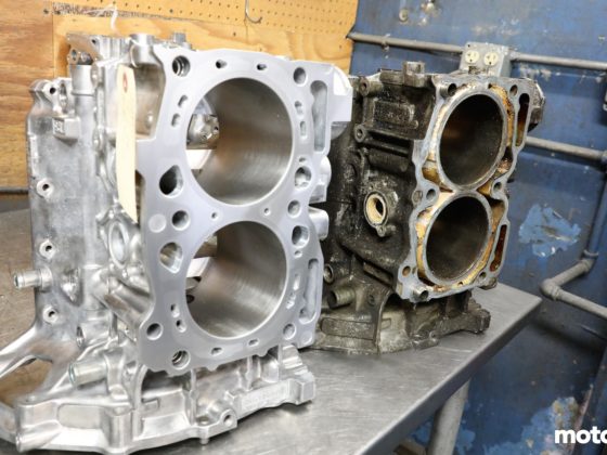
In Formula Drift, the unibody must remain stock between the frontmost suspension pick up point and the rearmost suspension pickup point. Beyond that, a pro car is typically a tube frame where the front and rear parts of the chassis can be unbolted and replaced or repaired quickly. The body panels are also fiberglass or carbon fiber and are also set up to be easily removable for easy repair and maintenance.

7 comments
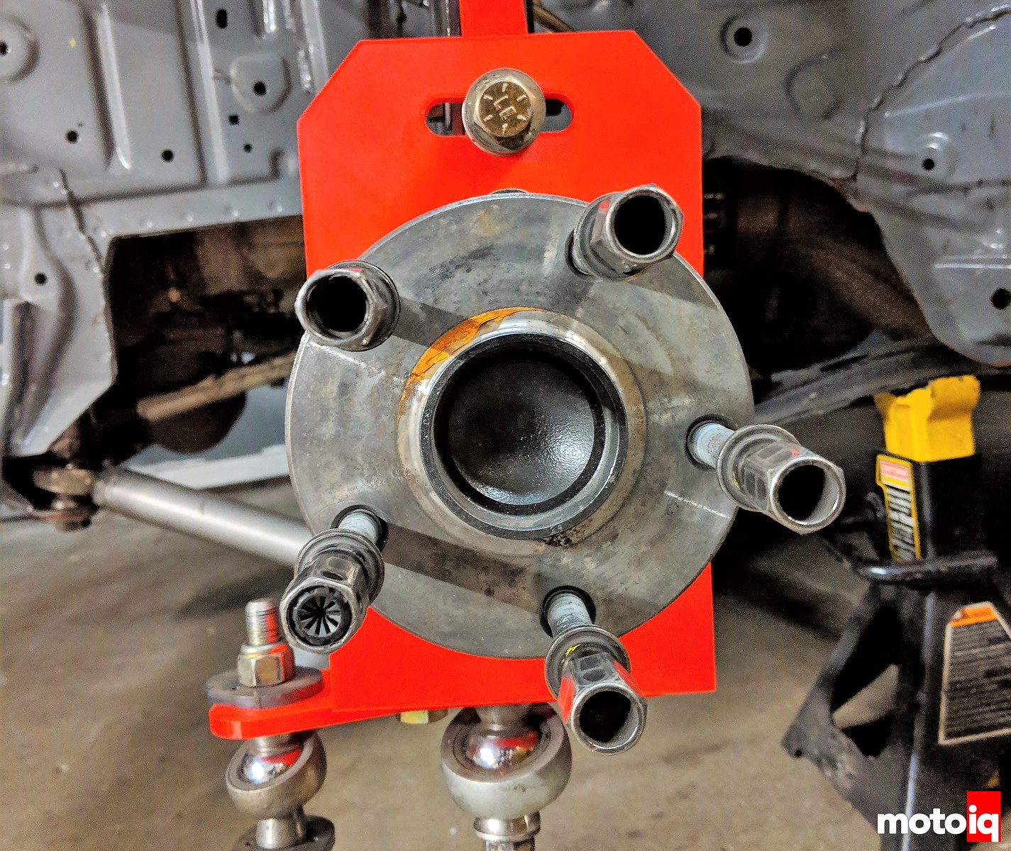
Nice setup, but just wondering about one thing: Why all the holes inside of it all? Wouldn’t it just be easier to make it in a flat panel without the holes? It’s probably done to reduce weight without a big compromise to strength, but i can imagine rubber debris is getting slewn in there?
Some of it is to reduce weight and also to get to the bolts holding the hub in. Debris can fall out the bottom easily and we have not had a problem with that issue. We design it to be pretty strong and the suspension links are the fuse in the design. We have stress riser failure points built into the arms so they will fail before the upright and chassis. This way we can repair the car in the allotted 5 minutes.
Ah right! I couldn’t see there where bolts inside, but that makes sense. Good thinking about the arms. Way less hassle to replace!
Cool. This validates my ideas on optimization of a drift car. Namely, the reduction of caster and Ackerman.
I learned a long time ago that caster (and dynamic camber gain) as the ‘secret’ to good turn-in ability. When you analyze your own footwork, you can see that your ‘outside foot’ digs in on the inside edge to initiate a turn. The same thing needs to happen with the tire footprint. The tire needs dynamic negative camber gain on the outside wheel, in order to initiate a turn to the inside. You can do this with SLA suspension, or by dialing up the caster on a strut equipped vehicle.
But, the same thing that helps a race car, works against a drift car, specifically because of the extreme steering angles. The driver has to fight against the wheel when the caster and Ackerman are high. Also, the drift car isn’t ‘turning’ in the conventional way, so you have to undo what works on one car, in order to optimize the other.
That is not how it works.
BTW, nice part design.
Totally unrelated to the knuckle design (which is really awesome), I noticed that you’re using the Hyperco articulating spring perch. Did they make a tangible difference? I hear they need frequent rebuilds.